Identify Stray Light in Imaging Systems with LightTools

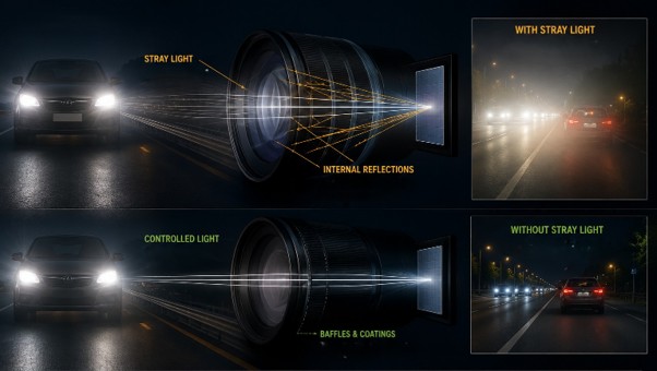
Stray light is undesired light radiation that interacts with the components of a system and degrades its performance by generating noise, that significantly reduces image quality and affects accuracy. These unintended reflections or scattering of light can be either from the object that the optical system is capturing or external emitters such as the sun or moon in case of cameras and telescopes.

Stray light could distort colours, prevent detection, affect contrast and data readability that tend to severely impact safety and efficiency. For example, the ADAS system in vehicles rely on multiple cameras for detection but the headlamps of on-coming traffic could affect the visual information being processed. Similarly, in medical imaging systems poor contrast and distortion could affect accurate diagnosis and treatment.

Fig.1. Examples of flare and ghost images in photos taken with a camera

To limit undesirable light reflections to a minimum, baffles, stop surfaces, or surface treatment/anti-reflective coatings can be used. However, the first step is to identify the source of stray light and examine the optical paths that create it.

Engineers can leverage LightTools optical design engineering software to accurately model the real-world performance of such systems and address stray light effects at the design stage itself, thus reducing multiple iterations and increasing efficiency.


LightTools Workflow For Stray Light Analysis

The aim is to examine the impact of reflections from lens surface and identify its optical path.

  • Open or import the lens model into LightTools. Align the geometry according to the global axis system and ensure all lens surfaces are grouped together and named sequentially.
  • Assign material properties to all components of the system, including lens, mirrors, baffles, mechanical mounts from the material library.
  • Choose optical property for the lens surfaces and the ray trace method. This defines if the surfaces will be reflecting, transmitting or has probabilistic ray split with Fresnel loss

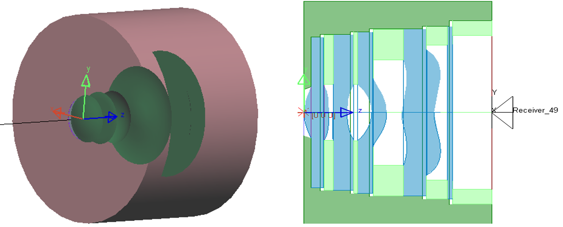
Fig.2. geometry of lens system in LightTools and its wireframe section view

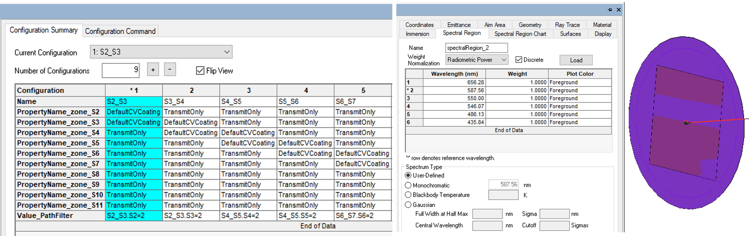
  • Multiple configurations with varying optical /material properties or any independent input variable can be created at once. This helps to evaluate more than one design concept simultaneously without needing to create the model from scratch.
  • Define an object source, this could simply be a rectangular plane source the size of the image or the actual image itself can be used as a source with the image processor utility.

Fig.3. define multiple configurations simultaneously(left) and a plane light source creation (right)

  • Multiple configurations with varying optical /material properties or any independent input variable can be created at once. This helps to evaluate more than one design concept simultaneously without needing to create the model from scratch.
  • Define an object source, this could simply be a rectangular plane source the size of the image or the actual image itself can be used as a source with the image processor utility.
  • Add receiver filter to the exit surface and input the ray trace parameters to run the simulation. Check the ray path collection is enabled for the receiver as this will record the complete data for each optical path traced through the system. Run the Monte-Carlo ray trace.
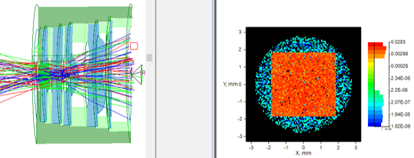
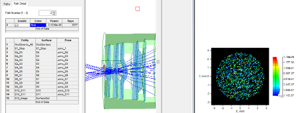
  • Analyse the Illuminance patterns for each configuration interactively or using the parameter analyser. The ray paths traversed through the system and its corresponding illumination pattern could be visualized individually using the Ray Path tool.

Fig.4. Visualizing rays traced through the system using Ray Path tool and its corresponding illuminance pattern

Fig.5. Ray path causing double reflections, path details and the corresponding stray light illuminance pattern produced


The tool provides complete data about the sequence of surfaces the rays are traced through and the total power, along with the illuminance pattern.

It assists engineers in detecting direct and single-bounce reflections from optical and mechanical surfaces, as well as where the ghost images will land, their size, and brightness, dependent on the geometry and coatings of each optical surface. Identifying the worst reflection pairs will help tweak the surface to reduce impact on final image.

By integrating Keysight LightTools into your early-stage workflow, you can proactively eliminate critical stray light and ghosting issues before they reach production

Redefining the Riding Experience with RAMSIS

In two‑wheeler design, comfort and safety start with the rider. RAMSIS (Realistic Anthropometric Mathematical System of Interior Comfort Simulation) is an ergonomic simulation platform that brings precise human modeling into the development of motorbikes and scooters. By combining large anthropometric databases, posture modeling, vision analysis, and reachability studies, RAMSIS lets designers evaluate how real people of different sizes interact with a vehicle long before any physical prototype exists.


Why Ergonomics And Anthropometry Matter For Two‑Wheelers

Ergonomics optimizes the fit between rider and machine; anthropometry supplies the measurements of human bodies. For two‑wheelers, small changes to handlebar height, seat shape, footpeg position, or mirror placement can dramatically affect comfort, fatigue, visibility, and control. Using anthropometric-driven simulation reduces costly late design changes and improves rider satisfaction across diverse populations.

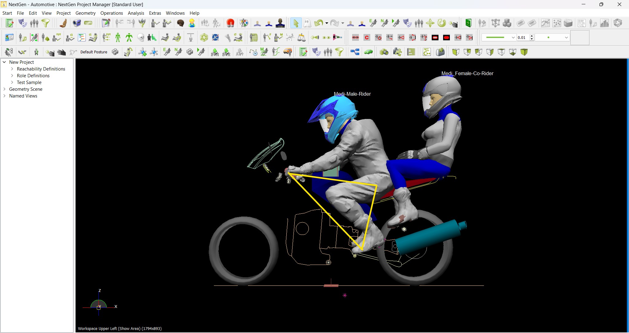
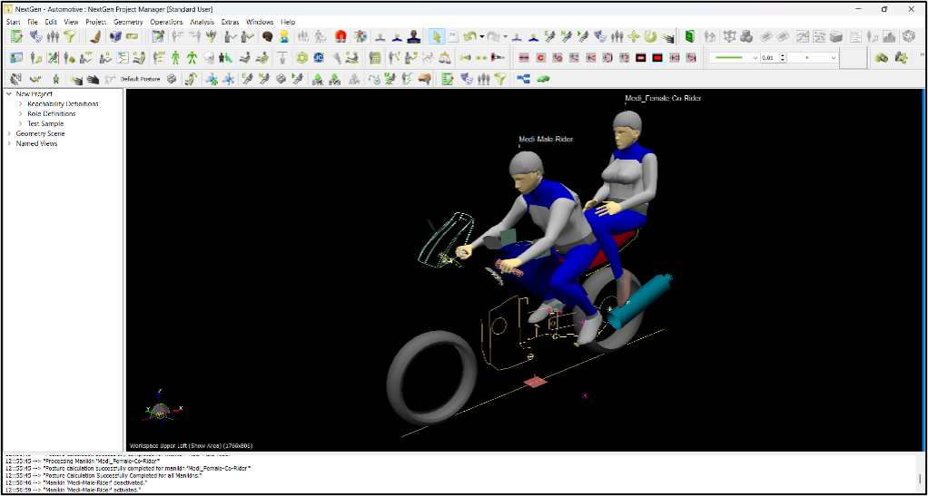
Fig 1: Shows Male Rider (50th percentile) and Female Pillion (50th percentile) withing RAMSIS standalone environment

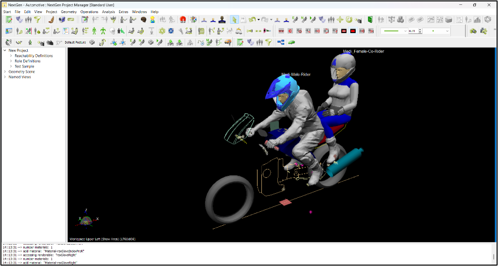
Fig 2: Shows Male Rider (50th percentile) and Female Pillion (50th percentile) withing RAMSIS standalone environment wearing Riding gears (RAMSIS equipment Library)

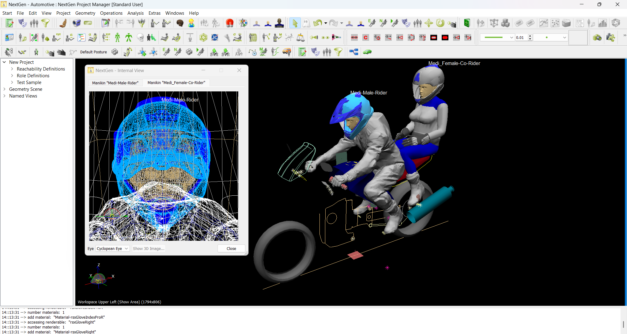
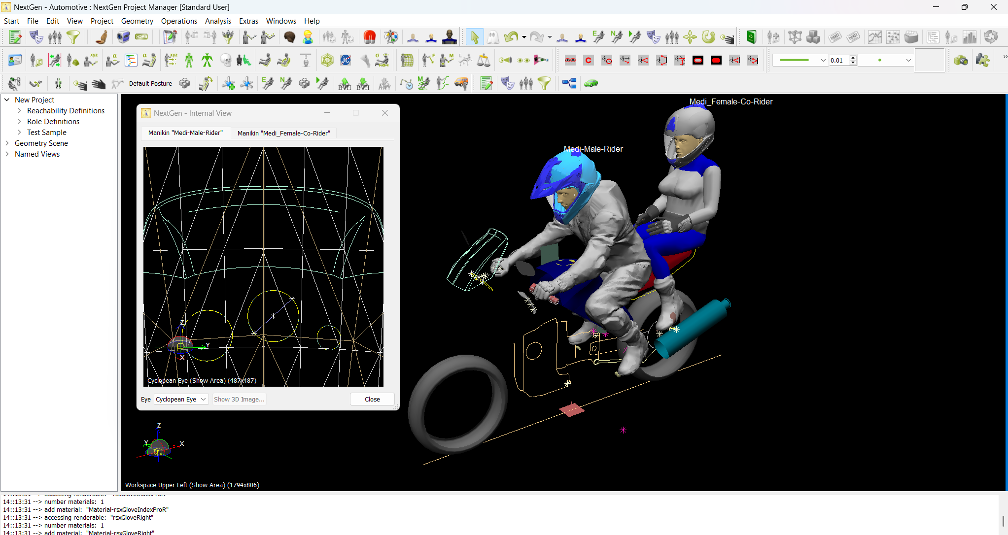
Fig 3: 50th Female Pillion Eye Vision

Fig 4: 50th Male Rider Eye Vision


Key RAMSIS Capabilities For Two‑Wheelers

  • Comprehensive anthropometric databases: Models draw from worldwide datasets (Germany, Japan/Korea, China, USA NHANES, India, Canada/LISA, Mexico, South America, France, and more) so designers test for regional body-size differences and global markets.
  • Automated posturing: Realistic rider postures for typical use (e.g., aggressive motorbike stance, upright scooter stance) are generated automatically to reflect natural seated positions.
  • Ground reachability analysis: Verifies whether riders of varying heights can plant feet safely when stopped, a critical safety and comfort metric for bikes and scooters.
  • Joint capacity and maximum force analysis: Assesses whether required steering, braking, or shifting forces exceed the comfort or strength limits of target user groups.
  • Vision and mirror analysis: Simulates sightlines and mirror fields to minimize blind spots and optimize mirror placement for both urban scooters and high‑speed bikes.
  • Rider triangle evaluation: Tests ergonomic relationships between seat, handlebars, and foot controls to ensure intuitive control and reduced rider strain.
  • Seat–manikin contact contour analysis: Visualizes contact between rider and seat to guide foam, shape, and contour design for long‑ride comfort.

Practical Applications In Motorbike And Scooter Development

  • Concept validation: Early-stage concepts can be checked for reach, posture, and visibility across percentile riders, avoiding costly rework.
  • Regional model tuning: Use region‑specific datasets (for example, Size India or Size North America) to tune geometry for local markets—seat height, peg position, and handlebar reach can be optimized per market.
  • Variant and accessory design: Test effects of different seats, windscreens, luggage racks, and handlebar risers on ergonomics before production.
  • Safety and usability testing: Evaluate emergency reach, mirror effectiveness, and steering forces to improve both comfort and crash preparedness.
  • Rider segmentation: Create target rider personas (commuter scooter rider, sport motorbike rider, touring rider) and tailor geometry and controls.

Example:
Designing a commuter scooter for India
Using India anthropometric data, designers run RAMSIS simulations to ensure shorter‑leg riders can still reach the ground comfortably, while also checking vision lines for typical urban traffic. Seat contour analysis helps shape a seat that reduces pressure points on long commutes. Results guide adjustments to seat height, floorboard shape, and mirror configuration before building prototypes.


Why OEMs And Designers Adopt RAMSIS

  • Faster, evidence‑based decisions that reduce physical prototyping.
  • Better market fit by validating designs for the demographics who will actually ride the product.
  • Improved rider comfort, safety, and satisfaction—key differentiators in competitive two‑wheeler markets.

Conclusion

RAMSIS turns anthropometry and ergonomics into actionable design intelligence. For motorbike and scooter manufacturers aiming to deliver comfort, control, and market‑fit, it’s a powerful tool to move from guesswork to human‑centred design.

Enhancing Product Understanding through 3D Technical Illustrator

The 3D Technical Illustrator role within the 3DEXPERIENCE Platform enables organizations to transform complex engineering data into clear, interactive, and visually rich technical documentation. In modern product development environments, where products are becoming increasingly complex, the need for accurate and easily understandable technical illustrations has become critical. This role bridges the gap between engineering design and end-user communication by leveraging model-based data directly from the digital product definition.


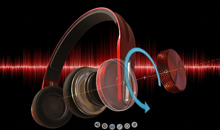
Fig: Exploring Product using 3D Technical Illustrator


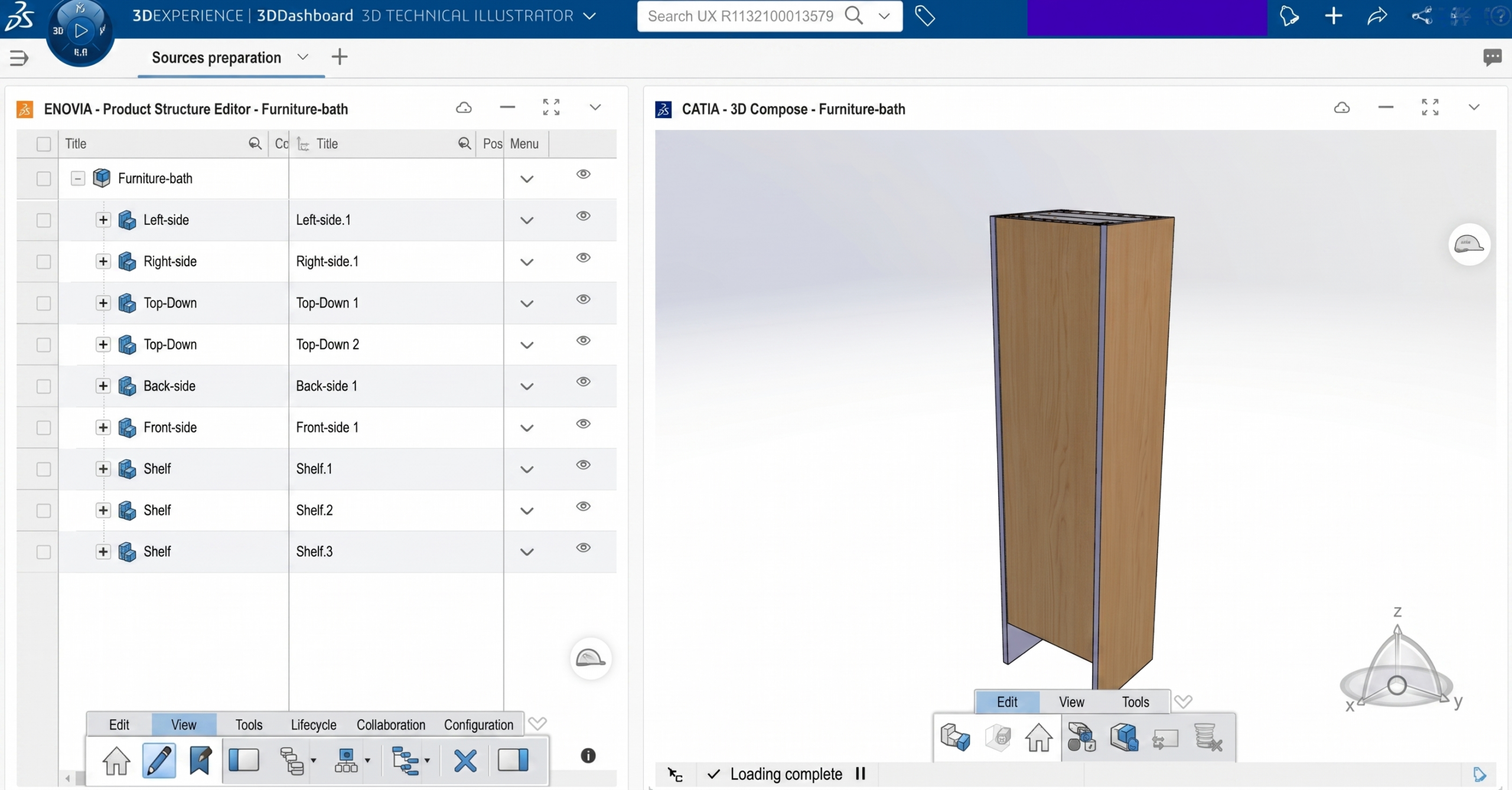
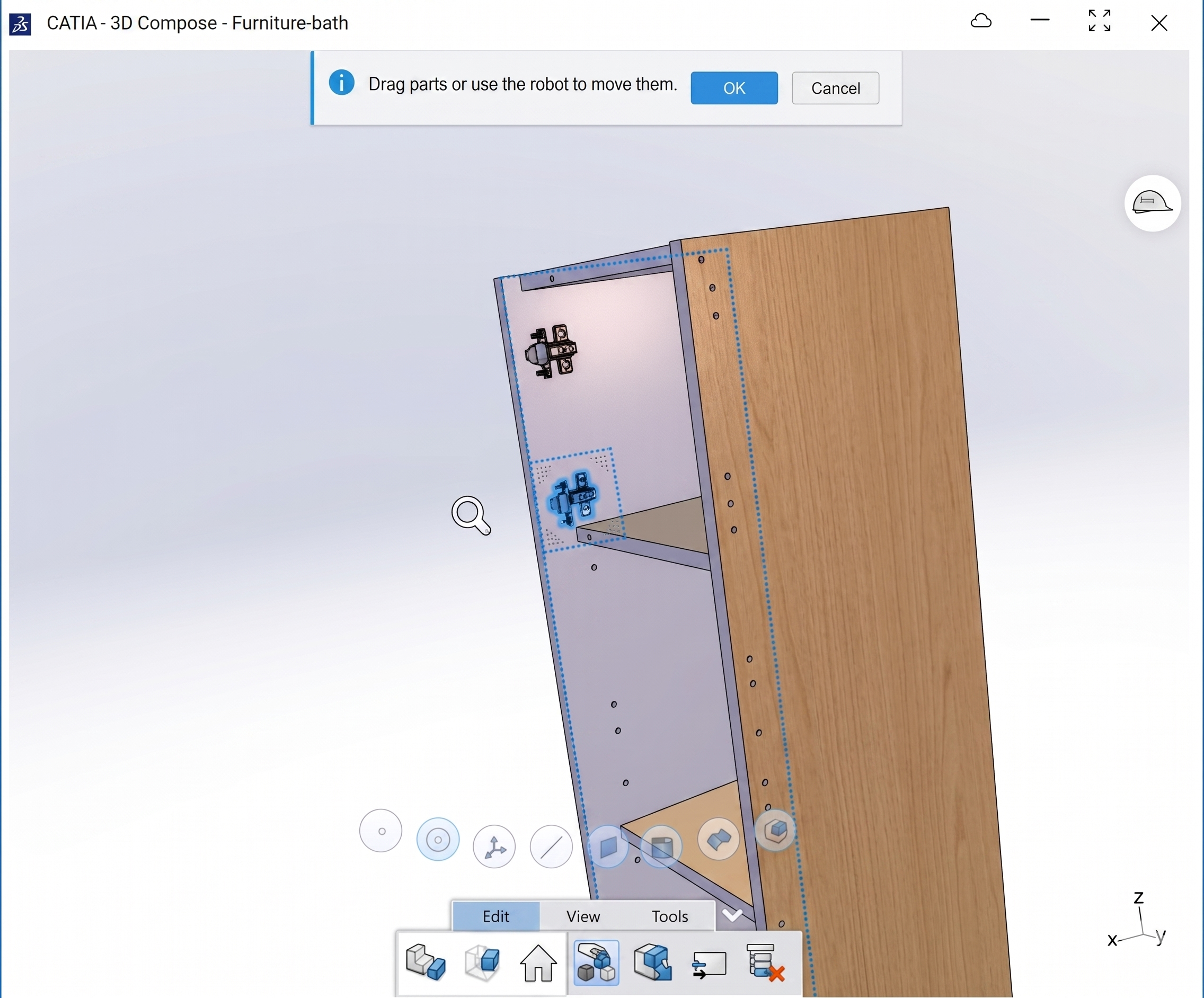
At the core of the 3D Technical Illustrator workflow is the ability to work with a complete product design, including standard components and assemblies. Designers and illustrators can enrich the product structure by organizing parts, defining positions, and preparing the model for downstream illustration purposes. Since the data is directly linked to the design environment, any updates made in the engineering phase are reflected in the illustrations, ensuring consistency and reducing rework.


Fig: Assembling the Components


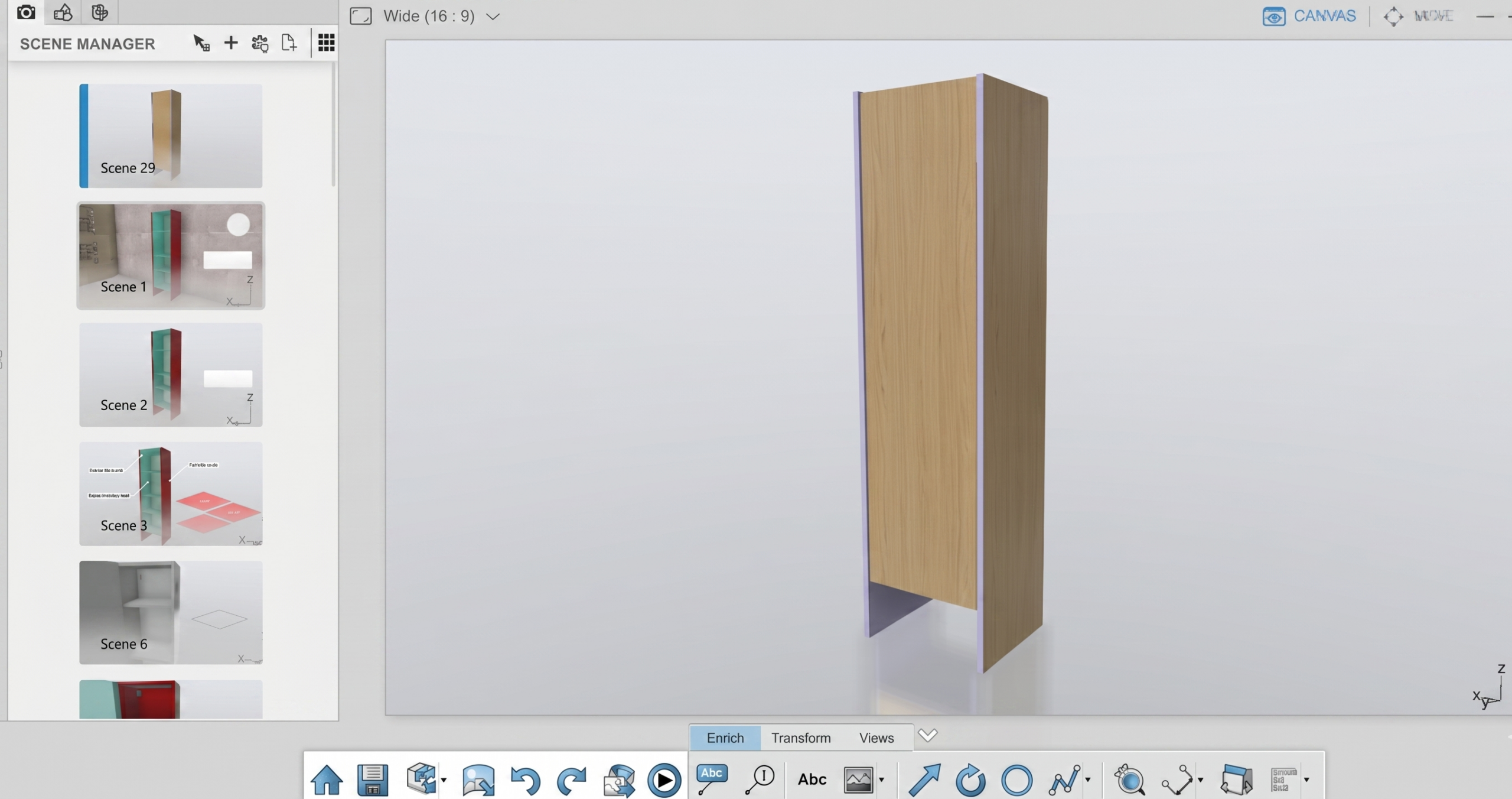
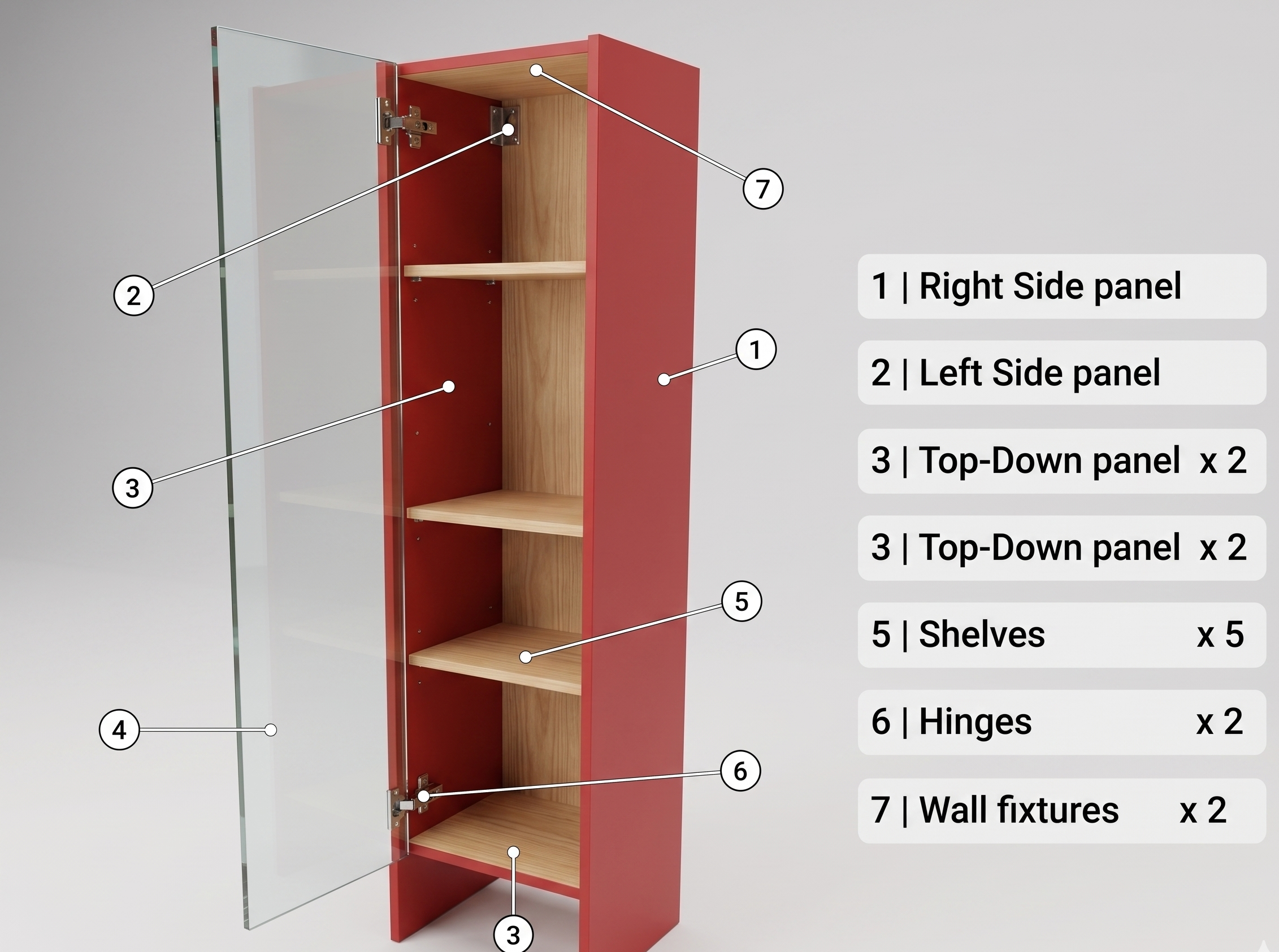
One of the most powerful capabilities of this role is the creation of detailed 3D illustrated views. These include exploded views that clearly show how parts are assembled or disassembled, making them especially useful for maintenance manuals and assembly instructions. Additional enhancements, often referred to as “dress-up,” allow illustrators to apply colors, annotations, callouts, and highlights to emphasize critical components or steps. This significantly improves clarity and usability for technicians and end users.


Fig: Creating Scenes for of the product showing different scenarios


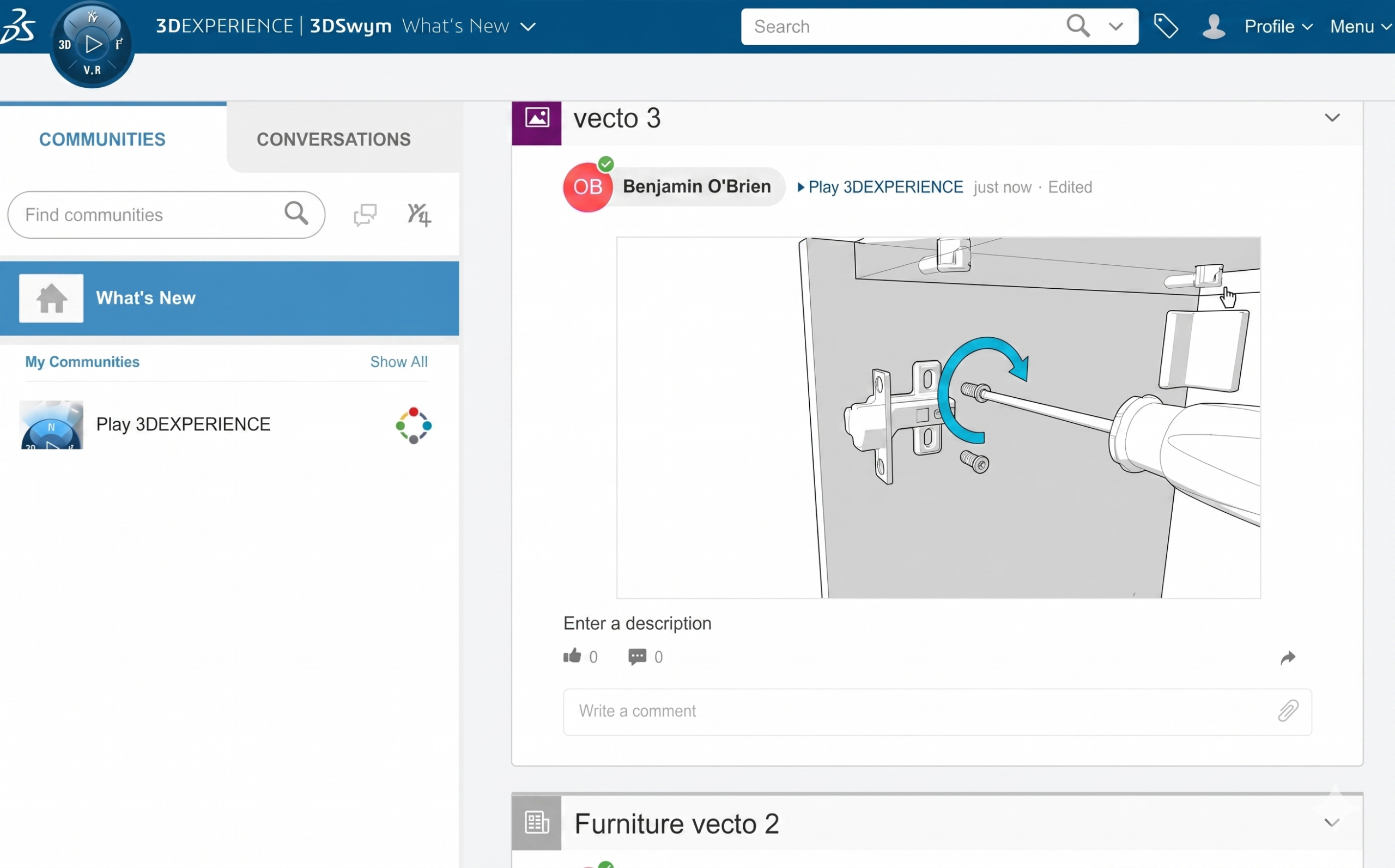
Beyond static visuals, the 3D Technical Illustrator supports the generation of both 2D and 3D outputs. High-quality raster and vector images can be produced and published directly to collaborative environments such as 3DDrive, 3DSpace, and Swym communities. These outputs are essential for creating technical publications like user manuals, service guides, and installation documents. Because they are derived from the 3D model, they maintain a high level of accuracy and visual consistency.


Fig: Posting the created 3D Technical Illustration on Swym community


In addition to traditional documentation, the role enables the creation of immersive 3D interactive experiences. These experiences allow users to explore products dynamically—rotating, zooming, and interacting with components to better understand functionality and assembly sequences. This is particularly valuable in industries such as automotive, aerospace, and industrial equipment, where visual comprehension can significantly improve efficiency and reduce errors.


Fig: Creating the annotations of the product


Another key capability is the production of video outputs. Animated sequences can demonstrate assembly procedures, maintenance workflows, or operational instructions in a step-by-step format. Compared to static manuals, these videos provide a more engaging and intuitive way to communicate complex processes, reducing training time and improving knowledge retention.

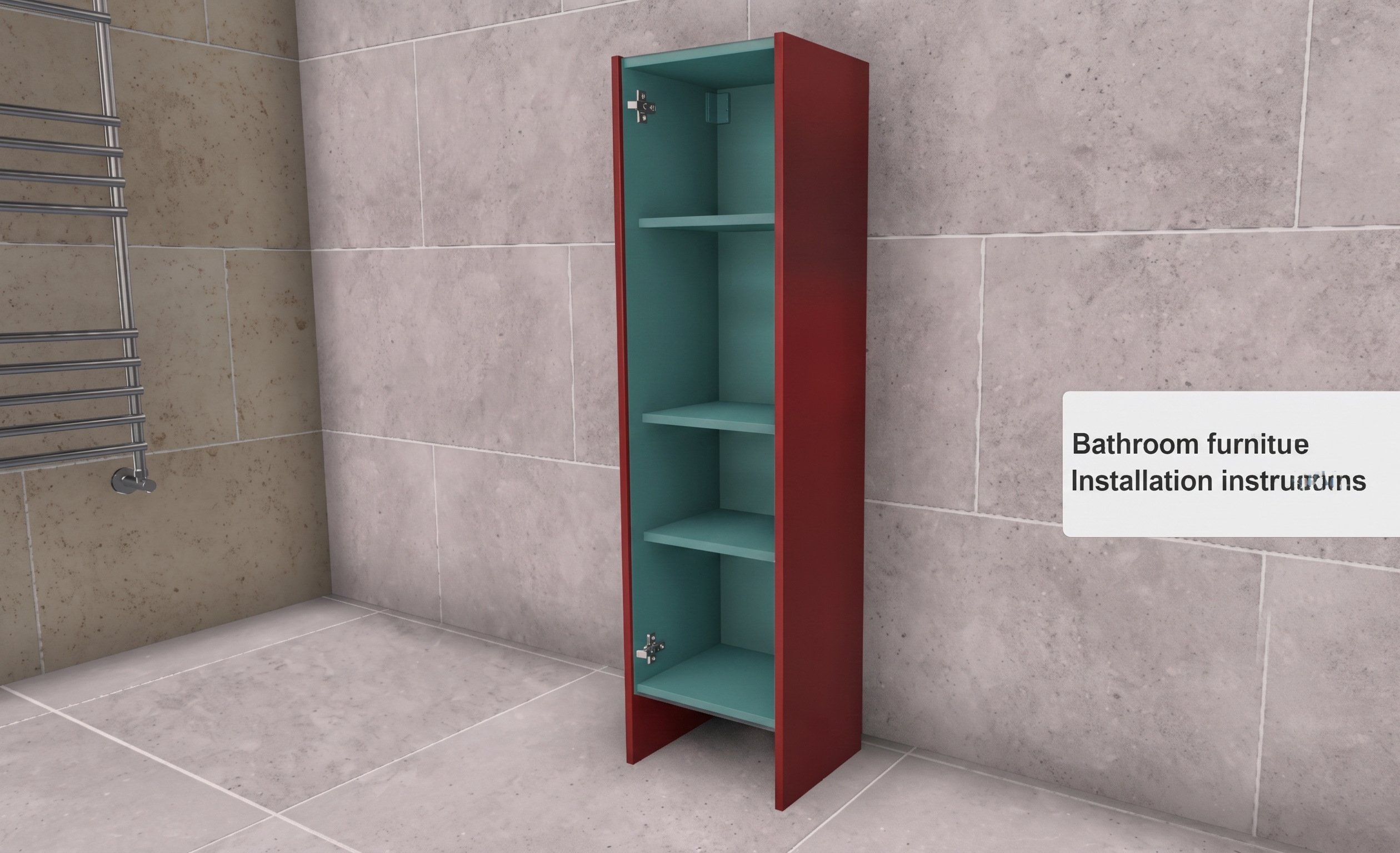
Fig: Product with background scenes as a bathroom furniture


The benefits of adopting the 3D Technical Illustrator role are substantial. Organizations can streamline the creation of technical documentation, reduce dependency on manual drafting, and ensure that all outputs are synchronized with the latest design data. This leads to faster documentation cycles, improved accuracy, and enhanced collaboration across teams. Moreover, the ability to deliver content anytime, anywhere, and on any device aligns with modern digital transformation goals.


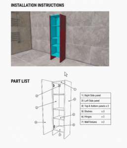
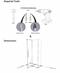
Fig: Technical Document created using 3D Technical Illustrator


In summary, the 3D Technical Illustrator role is a powerful extension of the digital engineering ecosystem. It transforms product data into meaningful technical communication assets, supporting everything from assembly instructions to interactive training materials. By integrating design, visualization, and collaboration within a unified platform, it enables organizations to deliver high-quality technical documentation that meets the demands of today’s complex product environments.
Transforming Physical Parts into Digital Models with CATIA 3DEXPERIENCE Reverse Engineer role

Reverse engineering has become a critical capability in modern product development, especially when working with legacy components, competitor benchmarking, or physical prototypes that lack digital design data. Within the CATIA 3DEXPERIENCE ecosystem, reverse engineering is not just about recreating geometry—it is about transforming real-world data into intelligent, parametric, and fully associative models that can be reused across the product lifecycle.

At its core, reverse engineering in CATIA 3DEXPERIENCE begins with data acquisition. Physical parts are typically scanned using 3D scanning technologies such as laser scanners or structured light scanners, producing dense point clouds or mesh data (STL format). These raw datasets often contain noise, irregularities, and gaps. The platform provides robust tools to clean and optimize this scan data, ensuring accuracy before moving to the modelling phase. This preprocessing step is crucial because the quality of the final CAD model heavily depends on how well the scan data is refined.

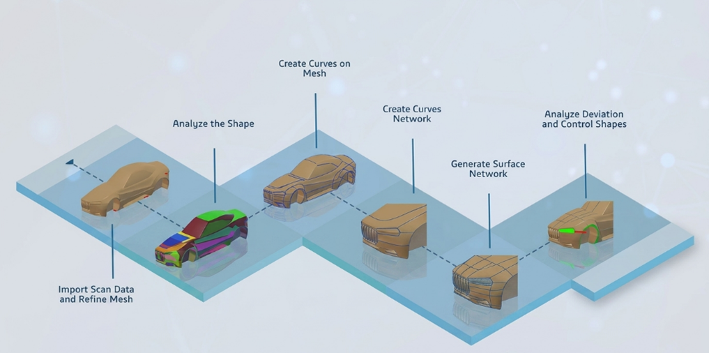
Fig 1: Reverse Engineering Workflow: From Scan to CAD


Once the scan data is prepared, CATIA 3DEXPERIENCE offers specialized roles such as Digitized Shape Preparation (DSP) and Digitized Shape Editor (DSE) to convert mesh data into usable surfaces. Engineers can segment the mesh, extract key features, and identify geometric patterns such as planes, cylinders, and freeform surfaces. This step bridges the gap between unstructured scan data and structured CAD geometry. Unlike traditional CAD modelling, where design intent is predefined, reverse engineering requires the engineer to interpret and reconstruct the design intent from the physical model.

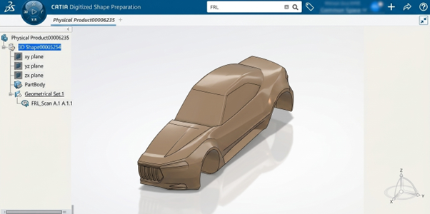
Fig 2: Imported Scanned data into 3DEXPERIENCE


A major advantage of reverse engineering in CATIA 3DEXPERIENCE is its ability to create parametric and feature-based models from scan data. Using advanced surfacing tools available in Generative Shape Design (GSD) and Freestyle workbenches, users can rebuild complex geometries with high precision. This is particularly useful in industries like automotive BIW (Body in White), where surface continuity (G2/G3) and accuracy are critical. The resulting model is not just a static representation—it is fully editable, allowing engineers to modify dimensions, apply constraints, and integrate it into assemblies.


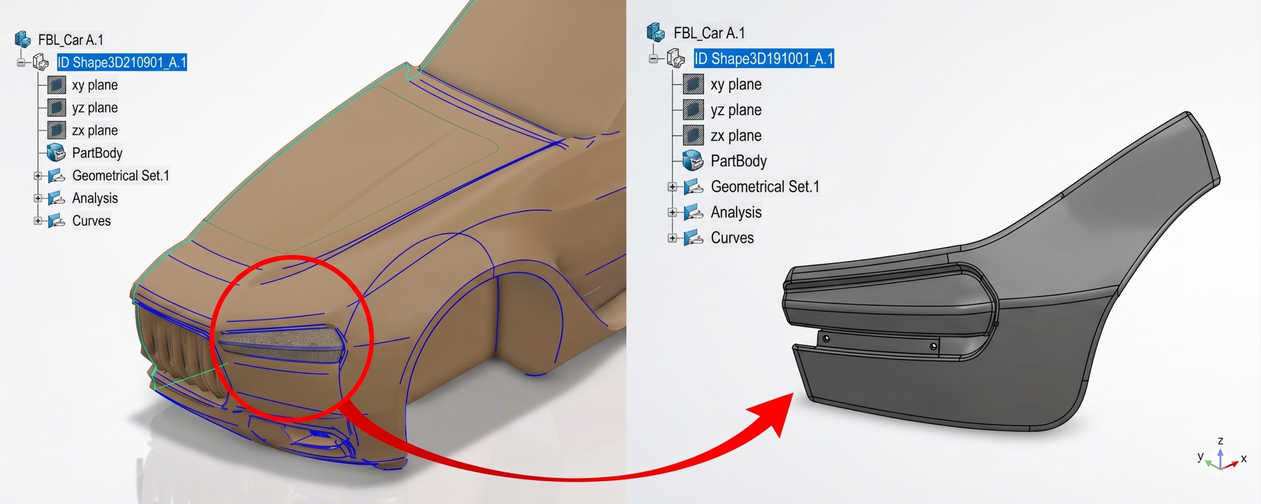
Fig 3: Creating curves and converting to Surfaces


Reverse engineering also plays a vital role in inspection and validation. By comparing the reconstructed CAD model with the original scan data, engineers can perform deviation analysis to identify manufacturing defects or wear and tear. CATIA’s integration with inspection tools enables color mapping and tolerance analysis, ensuring that the recreated model meets required specifications. This is especially valuable in quality control and remanufacturing scenarios.

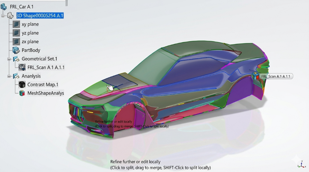
Fig 4: Mesh Shape Analysis showing colors based on topology.


From a collaborative standpoint, the 3DEXPERIENCE platform enhances reverse engineering workflows by enabling cloud-based data management and real-time collaboration. Teams can access scan data, CAD models, and analysis results in a unified environment, eliminating data silos. Integration with other roles across design, simulation, and manufacturing ensures that reverse-engineered models can seamlessly transition into downstream processes.

However, reverse engineering is not without challenges. Handling large scan datasets can be computationally intensive, requiring optimized hardware and data management strategies. Additionally, interpreting design intent from organic or highly complex shapes demands both technical expertise and domain knowledge. Despite these challenges, the capabilities offered by CATIA 3DEXPERIENCE significantly streamline the process and improve accuracy.

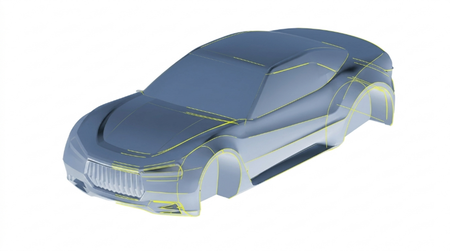
Fig 5: Final Product after Reverse Engineering


In conclusion, reverse engineering in CATIA 3DEXPERIENCE is a powerful enabler for innovation, especially in scenarios where original design data is unavailable. By combining advanced scanning integration, robust surfacing tools, parametric modelling, and knowledge-based automation, the platform transforms physical components into intelligent digital assets. For engineers working in domains like automotive tooling, aerospace, and industrial equipment, mastering reverse engineering in CATIA 3DEXPERIENCE can unlock new levels of efficiency, flexibility, and competitive advantage.


Fixing Search Service Down Issue in 3DEXPERIENCE Platform

Search is one of the most critical features in the 3DEXPERIENCE platform. If the search service goes down, users cannot find objects, documents, or data—impacting productivity immediately.

In this blog, we’ll cover how to troubleshoot and fix search service issues related to:

  • 3DSearch
  • Federated Search (FedSearch)
  • Indexing services

Common Symptoms

You may be facing a search service issue if:

  • Search returns no results
  • Search is very slow
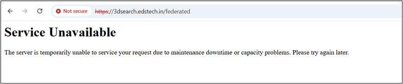
  • Error like “Search Service Not Available”
  • Infinite loading while searching
  • FedSearch not showing external results

Understanding How Search Works

In 3DEXPERIENCE:

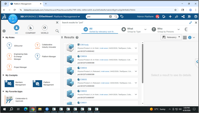
  • 3DSearch handles indexing and search queries
  • Data is stored in search indexes (similar to Elasticsearch concept)
  • Platform services communicate with search engine


If any of these components fail → search stops working.


Step-by-Step Troubleshooting Guide

Check Search Service Status

Login to server and verify services:

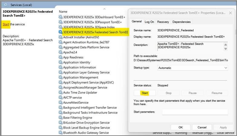
  • Check if 3DSearch service in services is running
  • On Linux: ps -ef | grep search
  • On Windows: Check in Services.msc


If service is stopped → start it.

Verify Platform Services

Ensure below services are up:

  • 3DSearch
  • 3DSpace
  • 3DPassport


If any service is down → restart all services in proper sequence.


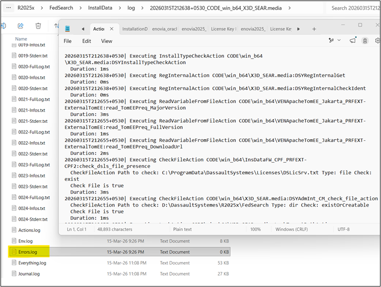
Check Logs (Most Important )

Go to log directory: <Install_Dir>/logs/

Check:

  • Search logs
  • TomEE logs
  • Platform logs


Look for errors like:

  • Connection refused
  • Index corruption
  • Out of memory

Check Indexing Status

Sometimes search is up but indexing is broken.

Symptoms:

  • Old data visible
  • New data not searchable


Fix:

  • Rebuild index from admin tools
  • Restart indexing service

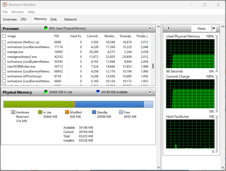
Disk Space & Memory Check

Search services require high resources.

Check: df -h, free -m

If disk is full or RAM is low:

  • Clean temp files
  • Increase memory


Check Port Availability

Search service runs on specific ports.

Verify ports are not blocked:

netstat -tulnp | grep <port>

If blocked:

  • Open firewall ports
  • Resolve conflicts

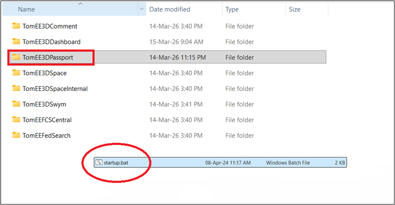
Restart in Correct Order

Recommended restart sequence:

Stop all services

Start:

  • Database
  • 3DPassport
  • 3DSearch
  • 3DSpace


Wrong order can cause service dependency failure.


Verify FedSearch Configuration

If Federated Search not working:

Check:

  • External connectors
  • Network access
  • Configuration in admin panel


Common Issues & Fixes

Issue: Search returns blank results

  • Cause: Index corruption
  • Fix: Rebuild index


Issue: Search service not starting

  • Cause: Port conflict / Java issue
  • Fix: Change port or check Java config


Issue: Slow search performance

  • Cause: Low memory
  • Fix: Increase JVM heap size


Issue: FedSearch not working

  • Cause: Connector misconfiguration
  • Fix: Reconfigure external search


Pro Tips (From Real Support Experience)

  • Always check logs first (saves time)
  • Maintain regular index rebuild schedule
  • Monitor server health (CPU, RAM, Disk)
  • Use dedicated server for search in large environments

Conclusion

Search-related issues in the 3DEXPERIENCE Platform are commonly caused by factors such as service downtime, indexing problems, or underlying resource limitations. By systematically addressing these areas, organizations can efficiently identify the root cause of the issue, restore search functionality, and enhance overall platform performance and user experience.

Common Installation Errors and How to Fix Them in 3DEXPERIENCE

The 3DEXPERIENCE Platform is a powerful solution used by industries worldwide for product lifecycle management (PLM), simulation, and collaboration. However, installing 3DEXPERIENCE—especially on-premise—can be complex and often leads to various errors.

In this blog, we will explore the most common installation errors and provide practical solutions to fix them.


ENOAppsCommon Error

Error : ENOAppsCommonAction failed

Cause:

  • Missing prerequisites
  • Incorrect environment variables

Solution:

  • Verify Java, Apache, TomEE versions
  • Set environment variables correctly
  • Run installer as Administrator


3DSpace Installation Failure

Error : MQL command failed

Cause:

  • Database misconfiguration
  • Missing tablespaces

Solution:

  • Create required tablespaces
  • Verify DB credentials
  • Check logs for failed commands


3DPassport Not Starting

Error : Service fails to start

Cause:

  • Missing database.properties
  • Wrong DB configuration

Solution:

  • Reconfigure database
  • Verify file path and permissions
  • Restart TomEE

3DDashboard Not Loading

Issue : Dashboard service not accessible

Cause:

Dependency services not running

Solution:

  • Start 3DPassport first
  • Check ports and logs

DSLS License Server Issue

Error : License not detected

Cause:

  • MAC ID mismatch

Solution:

  • Verify MAC address
  • Re-import license


SpaceIndex Installation Failure

Error : startupXL failed

Cause:

  • Corrupted files or consumed ports.
  • Missing dependencies

Solution:

  • Re-download media
  • Check system requirements


SSL Certificate Error

Error : ‘Not Secure’ in browser

Cause:

  • Certificate mismatch

Solution:

  • Generate correct SSL certificate
  • Update Apache config


Port Conflict Issue

Error : Service not starting due to port usage

Cause:

  • Port already in use

Solution:

  • Use netstat -ano to identify process
  • Change port in config files

Database Connection Failure

Error : Unable to connect to DB

Cause:

  • Wrong credentials
  • SQL Server not running

Solution:

  • Verify username/password
  • Check DB services
  • Allow TCP/IP in SQL Server


Java Version Mismatch

Error : Installation fails or services crash

Cause:

  • Unsupported Java version

Solution:

  • Install recommended JDK version
  • Update JAVA_HOME


Insufficient System Resources

Issue : Installation slow or stuck

Cause:

  • Low RAM/CPU

Solution:

  • Minimum 32GB RAM recommended
  • Use SSD storage

Permission Issues

Error : Access denied during installation

Cause:

  • Limited user privileges

Solution:

  • Run as Administrator
  • Provide full folder permissions


Antivirus or Firewall Blocking

Issue : Installation interrupted

Cause:

  • Security software blocking files

Solution:

  • Temporarily disable antivirus
  • Add installation folder to exceptions

Incorrect Hostname Configuration

Error : Services not accessible via URL

Cause:

  • Hostname not mapped properly

Solution:

  • Update hosts file
  • Verify DNS settings

Best Practices

  • Always follow official documentation
  • Prepare prerequisites in advance
  • Use recommended hardware
  • Monitor logs carefully
  • Take backup before installation

Conclusion

Installing the 3DEXPERIENCE Platform requires careful planning and correct configuration. Most errors are related to environment setup, database issues, or system limitations. By understanding these 12+ common issues, you can significantly reduce installation time and improve success rate.

Subscribe to our newsletter

Get all the latest information on Events, Sales and Offers.