From Classroom to Industry: Empowering Future Engineers with the 3DEXPERIENCE Platform

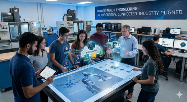
In today’s fast-evolving engineering and design landscape, educational institutions must go beyond conventional CAD teaching methods. While standalone tools like CATIA V5, SOLIDWORKS, or traditional engineering applications have served academia well for years, the industry has now shifted toward connected, collaborative, lifecycle-driven product development environments. The 3DEXPERIENCE platform by Dassault Systemes perfectly aligns with this transformation, providing universities, engineering colleges, technical institutes, and vocational training centres an industry-relevant digital ecosystem. Rather than just teaching software skills, institutions must now focus on building future-ready engineers, innovators, and digital manufacturing professionals—and 3DEXPERIENCE makes that possible.

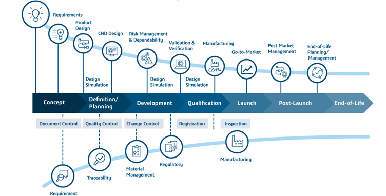
3DEXPERIENCE is not just another design software; it is a unified business and engineering platform that integrates design, simulation, manufacturing, collaboration, PLM, and data intelligence into one cloud or on-premises environment. Students learn how real companies operate—managing product structures, change processes, digital continuity, multidisciplinary collaboration, and traceability – skills that industries demand but most graduates lack. When students work within 3DEXPERIENCE, they experience complete product lifecycle workflows: ideation, conceptual design, detailed engineering, virtual validation, manufacturing planning, documentation, and governance. This transform’s learning from tool-usage to system-thinking and enterprise-level engineering understanding.

Fig- Product Lifecycle Management (PLM): From Concept to End-of-Life


One of the strongest reasons educational institutions need 3DEXPERIENCE is the shift toward collaborative product development. Modern engineering no longer happens in isolated silos. Automotive OEMs, aerospace manufacturers, robotics developers, consumer goods companies, and industrial equipment organizations all work in globally distributed teams. The platform enables role-based access, multi-disciplinary collaboration, and secured data sharing, allowing students to work like real enterprise teams. Faculty can assign team projects where mechanical, manufacturing, electrical, simulation, and management students collaborate on the same digital twin in real time. This nurtures teamwork, communication, leadership, and project management—critical employability skills.

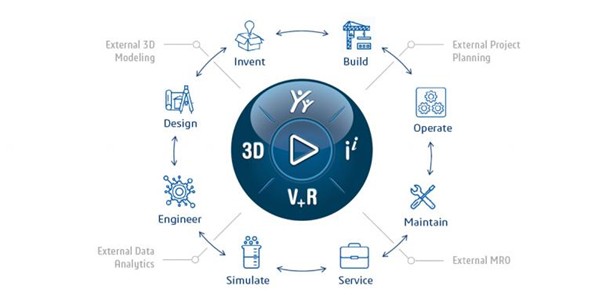
Another major benefit is exposure to digital twin and systems engineering methodologies. Today’s smart products integrate mechanical structures, electronics, embedded systems, connectivity, and software. 3DEXPERIENCE provides integrated capabilities like CATIA for advanced design, SIMULIA for multi-physics simulation, DELMIA for manufacturing and robotics, and ENOVIA for PLM governance. Students can design a part, simulate its structural performance, plan manufacturing, and manage revisions without leaving the platform. This reinforces the principles of Model-Based Engineering, enabling students to move naturally from designing 3D geometry to engineering behaviours, performance validation, and manufacturability assessment. This prepares them for Industry 4.0 and smart manufacturing environments.

Fig- 3DEXPERIENCE Platform: Connecting Design, Simulation, Manufacturing, and Service


For institutions focusing on research, innovation, startups, and incubation centers, 3DEXPERIENCE provides a robust backbone to accelerate projects and technology development. Whether it is EV design, UAV development, additive manufacturing, biomedical devices, smart mobility systems, or industrial automation, the platform supports advanced simulation, optimization, and virtual testing – reducing prototype cost and research iteration cycles. It also supports data management and IP protection, enabling institutions to securely manage research data and collaborative projects with industries. Access to enterprise-level tools allows students and researchers to work with the same digital infrastructure used by top OEMs worldwide.

From an academic administration perspective, 3DEXPERIENCE also helps institutions modernize their curriculum digitally. Faculty can track student work, evaluate digital submissions, manage versions, and assess engineering thinking rather than just final outputs. Cloud deployment allows remote learning, enabling students to access industry-class tools from anywhere, making it ideal for hybrid and online education models. With structured educational packages, certifications, and academic licensing, institutions can enhance their reputation, strengthen industry tie-ups, and improve student placement outcomes.


In summary, educational institutions need 3DEXPERIENCE not just to teach software, but to transform learning into industry-aligned engineering practice. It bridges the gap between classroom knowledge and enterprise reality, enabling students to gain hands-on exposure to collaborative engineering, PLM processes, systems integration, digital manufacturing, simulation-driven design, and digital twin methodologies. Institutions that adopt 3DEXPERIENCE position themselves as future-ready, empowering students with the competencies required for tomorrow’s engineering challenges and making them highly valuable to global industries. If the goal is to create innovative, skilled, and industry-ready engineers, the 3DEXPERIENCE platform is no longer optional – it is essential.

CATIA Composer – Transforming Engineering Data into Interactive Technical Documentation

CATIA Composer is a powerful desktop application from Dassault Systemes designed to transform engineering 3D CAD data into highly intuitive and interactive technical documentation. In today’s engineering and manufacturing environments, clear product communication is as important as design accuracy. Traditional documentation methods using 2D drawings, screenshots, and manually created illustrations often lead to errors, misinterpretations, and delays. CATIA Composer eliminates these issues by allowing organizations to directly reuse existing CAD data from platforms such as CATIA V5, 3DEXPERIENCE, SOLIDWORKS, and standard neutral formats like STEP, IGES, and JT, without requiring design rework or CAD expertise. This enables non-CAD users including manufacturing engineers, technical authors, service teams, and training departments to work efficiently with real engineering models.

One of the biggest advantages of CATIA Composer is its associative link capability. When there is an engineering change in the CAD model, documentation can be updated automatically, ensuring consistency between product evolution and technical publications. This significantly reduces effort, cost, and time while minimizing human dependency and interpretation errors. With CATIA Composer, organizations can create various types of deliverables, including manufacturing assembly instructions, service and maintenance manuals, spare parts catalogues, technical illustrations, interactive 3D content, training material, and even marketing visuals. Its lightweight environment and user-friendly interface allow users to generate exploded views, step-by-step assembly sequences, BOM tables, balloons, leader annotations, and safety indicators with high visual clarity.


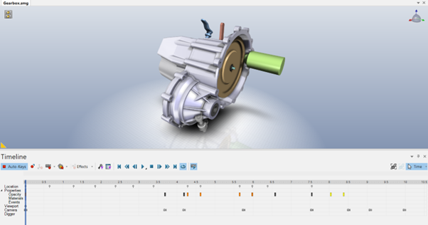
Fig- Dynamic assembly and Disassembly Sequence using timeline-based editing and keyframe controls


CATIA Composer also includes a robust animation engine that allows users to create dynamic assembly and disassembly sequences, maintenance steps, and operational demonstrations using timeline-based editing and keyframe controls. Visual techniques such as ghosting, transparency, section views, and cutaway animations enhance understanding of complex products. Technical illustration tools further enable generation of vector graphics, high-resolution images, and simplified line visuals suitable for manuals and compliance documentation.

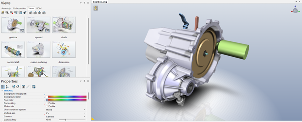
Fig- CATIA Composer Interface Displaying the Views Pane, Properties Panel, and 3D Model Workspace


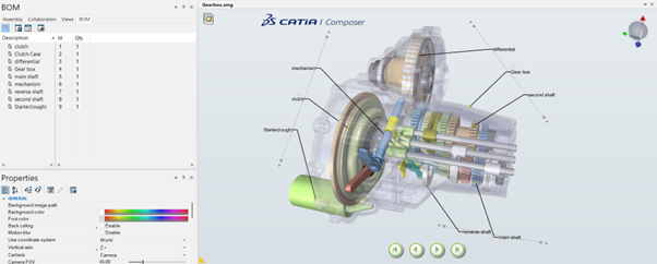
Composer automatically utilizes CAD metadata such as part numbers, descriptions, materials, and revisions, making BOM management and ballooning fast, accurate, and associative.

Fig- CATIA Composer Environment Showing BOM Management and Component Identification


The typical workflow in CATIA Composer begins with importing CAD data and defining product views such as exploded assemblies, service positions, and operational states. Users then apply annotations, BOM information, callouts, measurements, and procedural details. Animations or illustrations are created next, followed by publishing to various formats such as PDF, HTML, images, videos, and interactive SMG files. This flexibility allows organizations to distribute content digitally or traditionally based on requirement.

Fig: Modelled View of the component in Composer

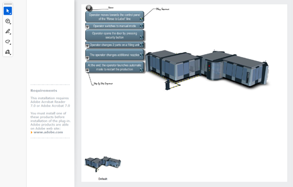
Fig: PDF Documentation Export from CATIA Composer


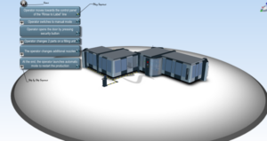
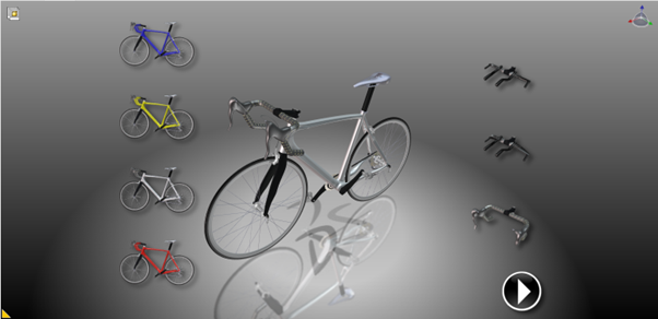
Compared to traditional documentation methods that rely on static screenshots and manually recreated illustrations, CATIA Composer enables the creation of interactive and dynamic technical content. The image illustrates how different product variants can be displayed and integrated within the main 3D model environment. When a specific variant is selected, the corresponding configuration is automatically shown in the central model view, allowing users to visualize design variations clearly. This interactive capability helps technical authors and engineers present multiple product configurations within a single documentation environment, improving clarity, accuracy, and user understanding while reducing the effort required to create separate illustrations for each variant.

Fig- Interactive Product Variant Selection in CATIA Composer

To gain maximum benefit, organizations should maintain structured CAD assemblies, ensure consistent metadata usage, plan documentation strategy early, and use Composer features like named views, layers, and controlled animations effectively. CATIA Composer is widely adopted across industries including automotive, aerospace, heavy machinery, industrial equipment, consumer electronics, and medical devices, where accurate assembly, manufacturing, and service communication is critical. Integrated within the 3DEXPERIENCE ecosystem, it supports managed data environments, secure collaboration, engineering change management, and lifecycle connectivity, creating a single source of truth between design and documentation.


In conclusion, CATIA Composer is more than a visualization tool; it is a strategic communication platform that bridges design, manufacturing, service, training, and customer communication. It enables organizations to produce high-quality, interactive, easily updatable technical content directly from engineering data, thereby reducing errors, improving productivity, supporting faster manufacturing readiness, enhancing service efficiency, and strengthening overall product communication quality. In a world where clarity equals reliability, CATIA Composer plays a vital role in delivering accurate and visually intelligent product information throughout the product lifecycle.

3DEXPERIENCE CATIA Composite Design – Delivering Next-Generation Precision for Advanced Composite Structures

3DEXPERIENCE CATIA Composite Design is an advanced, collaborative, and highly integrated engineering solution designed to manage the complexity of modern composite structures used across aerospace, automotive, marine, defence, energy, and high-performance industrial applications. Unlike conventional metallic parts, composite materials are engineered from multiple stacked plies with different orientations, materials, and thicknesses, where overall structural performance depends significantly on fiber direction, laminate sequence, and draping behaviour. The 3DEXPERIENCE platform elevates this capability further by providing a unified digital environment that connects design, simulation, manufacturing, and data management, ensuring composite development is accurate, traceable, and fully aligned with enterprise workflows.


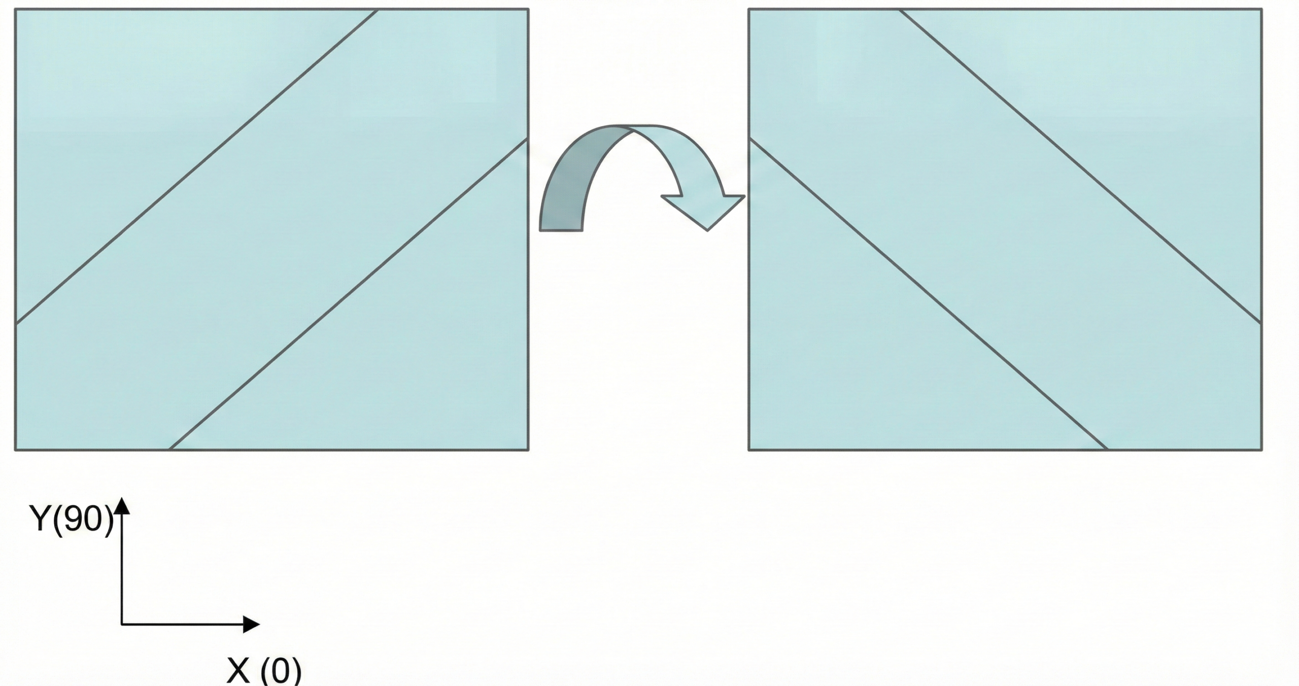
A key strength of 3DEXPERIENCE CATIA Composite Design is its robust ply-based design methodology, enabling engineers to build laminates layer by layer with exceptional precision. Each ply can be defined with exact boundaries, material definitions, thickness, fiber orientations (0°, ±45°, 90°, or custom), and stacking sequences, while zones and groups help manage large and complex components efficiently. The platform provides powerful draping simulation capabilities that allow designers to visualize how composite material behaves on curved or freeform surfaces and automatically adapts ply geometry to minimize wrinkles, overlaps, fiber distortion, and misalignment. This ensures that designs are not only structurally accurate but also realistic for manufacturing conditions.

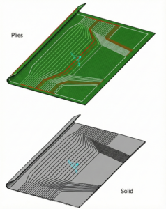
Fig- Ply Fiber Direction


Visualization, validation, and decision-making are significantly enhanced in 3DEXPERIENCE CATIA. Engineers can review laminate buildup step-by-step, analyse thickness variations, verify stack sequences, and evaluate overlaps and gaps with high clarity. Composite grid definitions and fiber direction maps support continuity and precision across complex aerodynamic, structural, or ergonomic surfaces. With the platform’s integrated data management capabilities, every design iteration remains traceable, controlled, and synchronized, reducing the risk of errors and rework while strengthening digital continuity from concept to production.


Another major advantage of 3DEXPERIENCE CATIA Composite Design is its strong alignment with manufacturing needs. The system supports automated flat pattern generation while considering draping effects and real fiber behaviour. Engineers can produce ply books, detailed manufacturing documentation, optimized nesting layouts, and laser projection data to support both manual lay-up and automated fiber placement processes. Through the unified 3DEXPERIENCE ecosystem, manufacturing teams, engineering teams, and suppliers can collaborate seamlessly, enabling faster decision-making, reduced material waste, shorter lead times, and higher production reliability.

From a structural performance perspective, 3DEXPERIENCE CATIA connects seamlessly with SIMULIA tools such as Abaqus for advanced composite analysis. Laminate definitions, stacking sequences, material details, and fiber orientations can be transferred directly for simulation to assess stiffness, load-bearing capability, failure criteria, delamination risks, fatigue performance, and optimization opportunities. This integrated simulation-driven design approach enables engineers to validate concepts early and refine them efficiently within the same platform without losing design intent or data integrity.


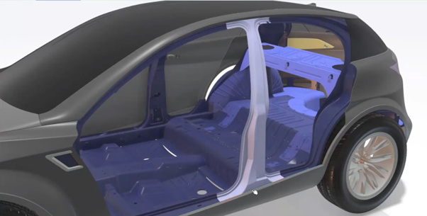
Fig- Solid representation of Plies


In conclusion, 3DEXPERIENCE CATIA Composite Design offers a comprehensive, intelligent, and collaborative environment for engineering composite structures with unmatched accuracy and efficiency. By integrating detailed ply-based modeling, advanced visualization, manufacturability assessment, enterprise collaboration, and simulation connectivity within a single platform, it empowers industries to deliver lighter, stronger, and more reliable composite products. Organizations benefit from reduced development cycles, enhanced product quality, minimized manufacturing risks, and accelerated innovation. For companies looking to master composite engineering while ensuring digital continuity and manufacturing readiness, 3DEXPERIENCE CATIA Composite Design stands as a future-ready and industry-leading solution

Keysight Optical Simulation Solutions: Innovation in Optical Design

Leveraging Keysight’s portfolio of optical and photonic design and simulation software one can accurately model all facets of an optical system. These advanced and interactive tools enable design of complex imaging systems, illumination devices, automotive lighting systems and photonic devices.


Achieve Optical Innovation with Keysight’s Optical Design Engineering software

LucidShape: Comprehensive automotive lighting solution

The LucidShape product family is a reliable engineering solution for design, simulation, visualization and validation of automotive lighting systems.

It includes modules to streamline shape creation and simulation of exterior automotive lighting systems.

  • Calculates optical geometries and creates optics based on freeform design
  • Simulate light sources, surfaces, materials, and sensors.
  • Use physics-based visualization tools for photorealistic images and simulations.
  • Automatic light guide construction, ray tracing, analysis and optimization tools.

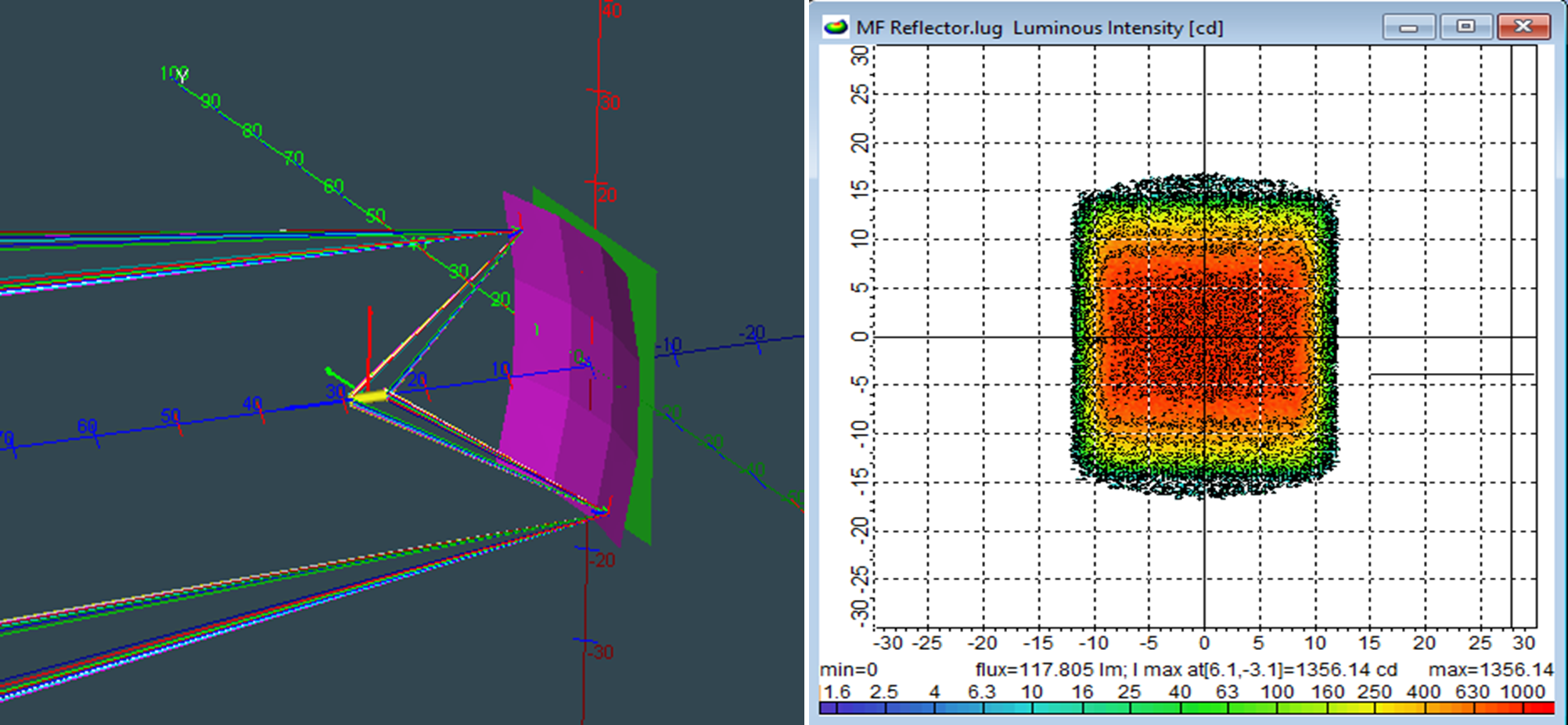
Fig.1: Freeform Macrofocal Reflector and it’s corresponding spread distribution in LucidShape.


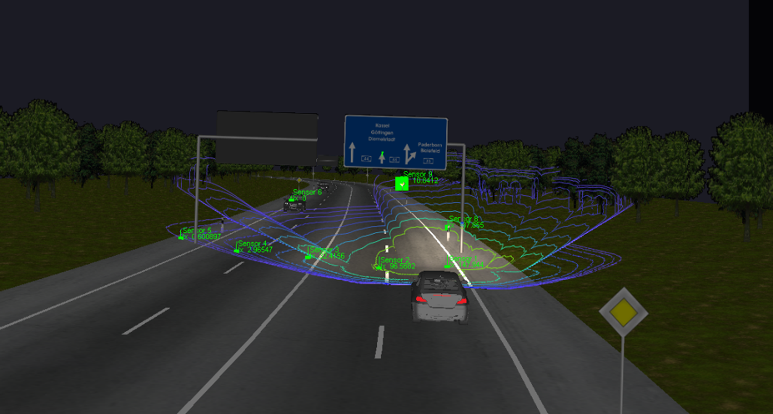
LucidDrive, a night driving simulator generates realistic beam pattern evaluations for vehicle headlamps to ensure optimal performance in real-world conditions. Helps assess adaptive front lighting systems like Pixel and Matrix beam headlamps by simulating their response to dynamic traffic conditions.

Fig.2: Matrix headlamp validation for traffic scenarios in LucidDrive, night driving simulator.


LightTools: Illumination Design Software

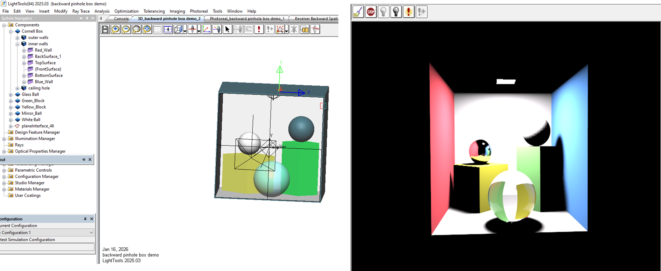
This 3D design software supports virtual prototyping, simulation, optimization and photorealistic rendering of illumination applications including LEDs, light guides for ambient lighting and backlit display systems (AR/VR devices).

It offers superior non-sequential ray tracing and advanced material libraries for modelling various surfaces as some of its key capabilities for designing backlight display systems, digital projectors, luminaires and ambient lighting components.

Fig.3: 3D modelling and photorealistic rendering of various surfaces under illumination as simulated in LightTools.


CODE V: Imaging System Design

Development of imaging systems including photographic, mobile camera and zoom lens, as well as free space photonic devices can be accelerated with CODE V’s advanced optimizing and tolerancing features.

  • Visualize optical system performance with image simulation.
  • Speed time to market with utilities like glass expert and asphere expert.
  • Multi-environment coupling model’s substrate changes due to temperature, pressure and mounting variations.

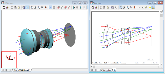
Fig.4: 2D schematic and 3D rendering of a lens with paraxial ray trace as seen in CODE V.


RSoft: Photonic Device Design

Comprises a wide portfolio of simulators and optimizers for active and passive photonic devices such as lasers, sensors and many more.

  • FulWave FDTD – study propagation of light in structures such as waveguides
  • DiffractMOD – tool for diffractive structures like DOE, photonic crystals
  • BandSOLVE – automates the modeling and calculation of photonic band structures
  • LaserMOD – simulates the optical, electronic and thermal properties of semiconductor lasers.

Optical Scattering Measurement Instruments

 Quickly and accurately quantify the light propagated from any surface or material depending on the angle of incidence, wavelengths, polarization, and observation angle. Helps identify imperfections in optical surfaces or light reflections off mechanical elements.

  • Mini Diff V2 – portable device that measures BRDF and BTDF with fixed AOI.
  • Mini Diff VPro – provides BRDF, BTDF and TIS Measurements with choice of AOI.
  • TIS Pro – features an integrated sphere and spectral detector to measure reflectance, transmittance and absorption.

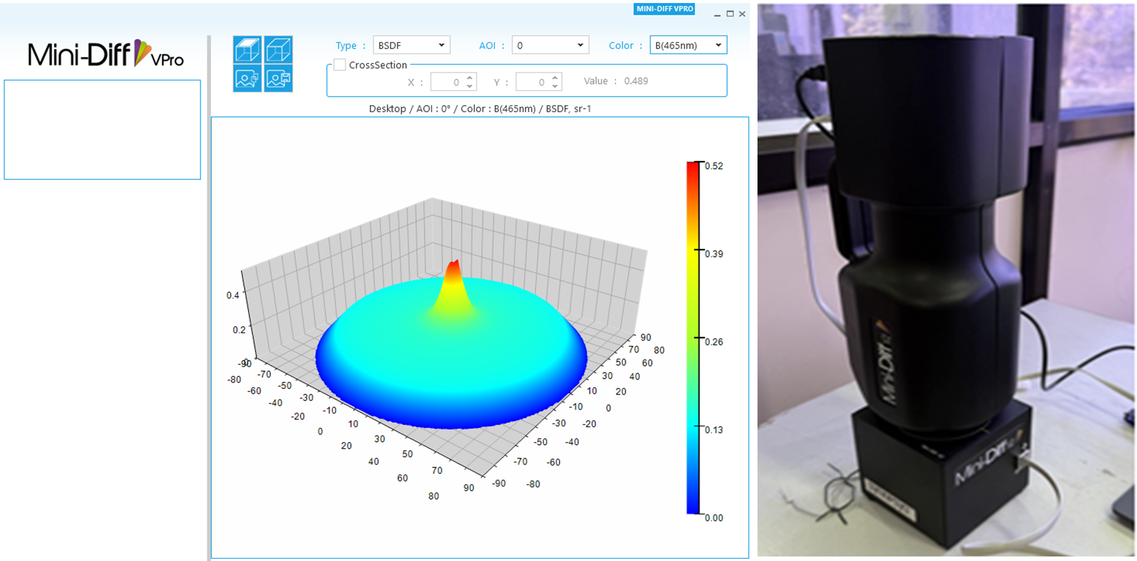
Fig.5: Mini Diff V2 device for measuring the BRDF and BTDF or various surfaces based on AOI


Maximize your design potential and bring concepts to reality by leveraging Keysight’s end-to-end optical design and virtual prototyping suite. Model light propagation with precision ensuring your innovations are as accurate as they are dazzling.

Parametric Modeling to Improve Design Efficiency in 3DEXPERIENCE CATIA

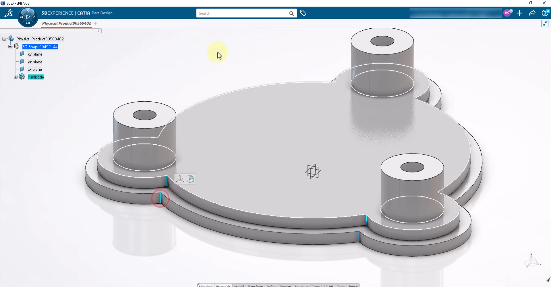
Parametric modeling is more than applying dimensions and constraints – it is about capturing design intent so that changes can be made without rework. In 3DEXPERIENCE CATIA, well-planned parametric models reduce redesign time, improve collaboration, and ensure long-term stability. 

This blog focuses on core principles which describe how parametric modelling improves design efficiency. 


Design Intent is the Foundation 

Efficient models start with a clear understanding of what will change and what must remain constant. Before creating geometry, identify functional dimensions, interfaces, and relationships between features. 

Defining design intent early allows CATIA parameters and formulas to control geometry predictably. Models built without intent often fail when updates are required later in the development cycle.


Sketch Quality Determines Model Stability 

A model is only as strong as its sketches. Fully constrained sketches ensure predictable behaviour and prevent unintended geometry movement. 

Avoid over-dimensioning; rely on geometric constraints such as symmetry, parallelism, and concentricity. This approach simplifies modifications and clearly communicates intent to team members. 


Use Stable References, Not Faces 

Excessive reliance on face-based references is a common cause of model failure. Faces may change or disappear, breaking dependent features. 

Instead, use datum planes, axes, published geometry, or master sketches. Stable references are especially important in parametric and top-down designs, keeping models resilient to changes. 


Keep the Feature Tree Structured 

A clean, organized feature tree improves performance and collaboration. Name features logically and arranges them in design order, not creation order. 

Place reference geometry at the top, core shape features in the middle, and finishing features such as fillets and chamfers at the end. This structure makes troubleshooting and future modifications easier. 


Drive Geometry with Parameters 

Manual edits defeat the purpose of parametric modeling. Key dimensions should be driven by parameters and formulas that reflect functional relationships. 

For instance, wall thicknesses, hole depths, and clearances can link to primary dimensions. This ensures consistent updates and reduces design errors. 


Apply Finishing Features Last 

Fillets and chamfers are important but fragile. Applying them too early can cause failures during updates. 

Treat finishing features as final operations and group them together. This makes it easy to modify or suppress them during redesigns. 


Plan for Change Before Release 

A robust parametric model should be tested by modifying key dimensions to ensure the geometry reacts predictably. This “what-if” validation confirms readiness for lifecycle progression. 

In a collaborative 3DEXPERIENCE environment, this step is critical before moving a model to Frozen or Released states. 


Conclusion 

Professional parametric modeling in 3DEXPERIENCE CATIA relies on clarity, structure, and foresight. Models with stable references, clean sketches, and meaningful parameters adapt smoothly to change and support efficient team collaboration. 

By applying these principles, designers can reduce rework, improve model reliability, and accelerate product development. 

Configuring Collaborative Spaces in 3DEXPERIENCE for Large Teams

In large organizations, effective collaboration is critical. 3DEXPERIENCE provides Collaborative Spaces, enabling teams to work concurrently on designs, manage data securely, and maintain version control. Proper configuration ensures efficiency, security, and traceability, even with dozens or hundreds of users.

This article outlines best practices for setting up Collaborative Spaces for large teams.


Understand Collaborative Spaces

A Collaborative Space in 3DEXPERIENCE is a virtual workspace where users can:

  • Store and manage parts, assemblies, and drawings
  • Control lifecycle states and revisions
  • Collaborate in real time with team members

For large teams, Collaborative Spaces are central hubs, ensuring that everyone works with up to date, validated data.


Define Roles and Permissions

Large teams need clear responsibilities. In 3DEXPERIENCE, roles control access, edit rights, and lifecycle actions.

Best practices:

  • Assign Designers full access to in-progress models.
  • Assign Reviewers/Managers read or approval permissions.
  • Use Observers for stakeholders who need visibility without editing rights.

This prevents accidental modifications and maintains data integrity.


Organize Work by Project or Product

For large teams, structure matters. Create Collaborative Spaces based on:

  • Project (e.g., “Electric Vehicle Chassis”)
  • Product line (e.g., “Engine Components”)

Within each space, you can further organize by functional areas (mechanical, electrical, or design phases). A clear hierarchy reduces confusion and improves data retrieval.


Use Lifecycle and Revision Control

Lifecycle management ensures that data moves from work-in-progress to released status in a controlled manner.

Tips:

  • Set In Work → Frozen → Released states for parts and assemblies.
  • Implement Change Actions for post-release modifications.
  • Track revisions carefully to ensure traceability and accountability.

Proper lifecycle configuration prevents errors and ensures compliance across teams.


Enable Real-Time Collaboration

For large teams, simultaneous work is key. Use 3DEXPERIENCE features like:

  • Locking objects during editing to avoid conflicts
  • Real-time comments and markups for design reviews
  • Dashboards to monitor team activity and pending approvals

This keeps everyone aligned and reduces redundant work.


Implement Naming and Data Standards

Consistency reduces confusion in large teams. Define:

  • Standardized file and part naming conventions
  • Metadata rules for parts (material, size, function)
  • Templates and master assemblies for recurring designs

These standards make searching, reporting, and collaboration seamless.


Monitor and Audit Spaces Regularly

For teams of 20+ designers, periodic auditing is essential:

  • Review access and permissions
  • Validate data integrity and lifecycle compliance
  • Archive obsolete or inactive projects

This keeps Collaborative Spaces organized and ensures long-term usability.


Conclusion

Configuring Collaborative Spaces in 3DEXPERIENCE properly is essential for large teams to collaborate efficiently and safely. Clear roles, structured workspaces, lifecycle management, and standardized data practices enable teams to deliver high-quality designs faster, reduce errors, and maintain compliance.

Subscribe to our newsletter

Get all the latest information on Events, Sales and Offers.