Enhancing Product Understanding through 3D Technical Illustrator

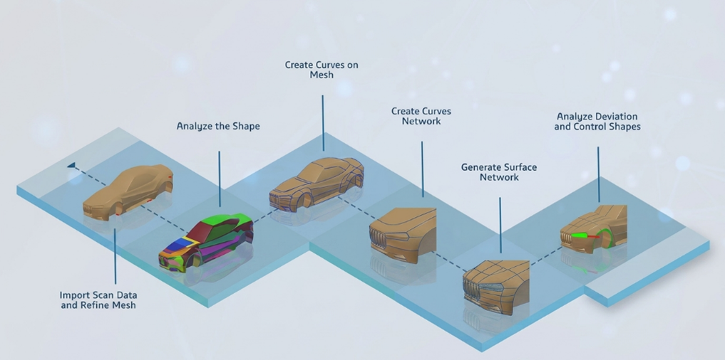
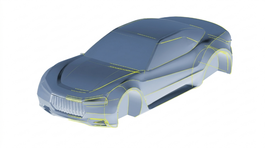
The 3D Technical Illustrator role within the 3DEXPERIENCE Platform enables organizations to transform complex engineering data into clear, interactive, and visually rich technical documentation. In modern product development environments, where products are becoming increasingly complex, the need for accurate and easily understandable technical illustrations has become critical. This role bridges the gap between engineering design and end-user communication by leveraging model-based data directly from the digital product definition.


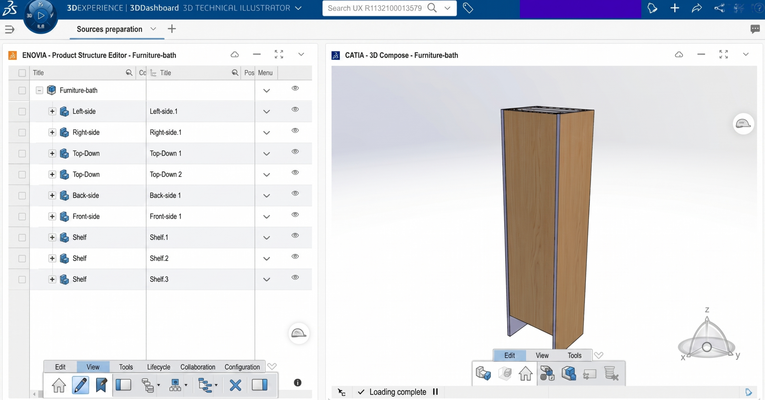
Fig: Exploring Product using 3D Technical Illustrator


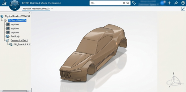
At the core of the 3D Technical Illustrator workflow is the ability to work with a complete product design, including standard components and assemblies. Designers and illustrators can enrich the product structure by organizing parts, defining positions, and preparing the model for downstream illustration purposes. Since the data is directly linked to the design environment, any updates made in the engineering phase are reflected in the illustrations, ensuring consistency and reducing rework.


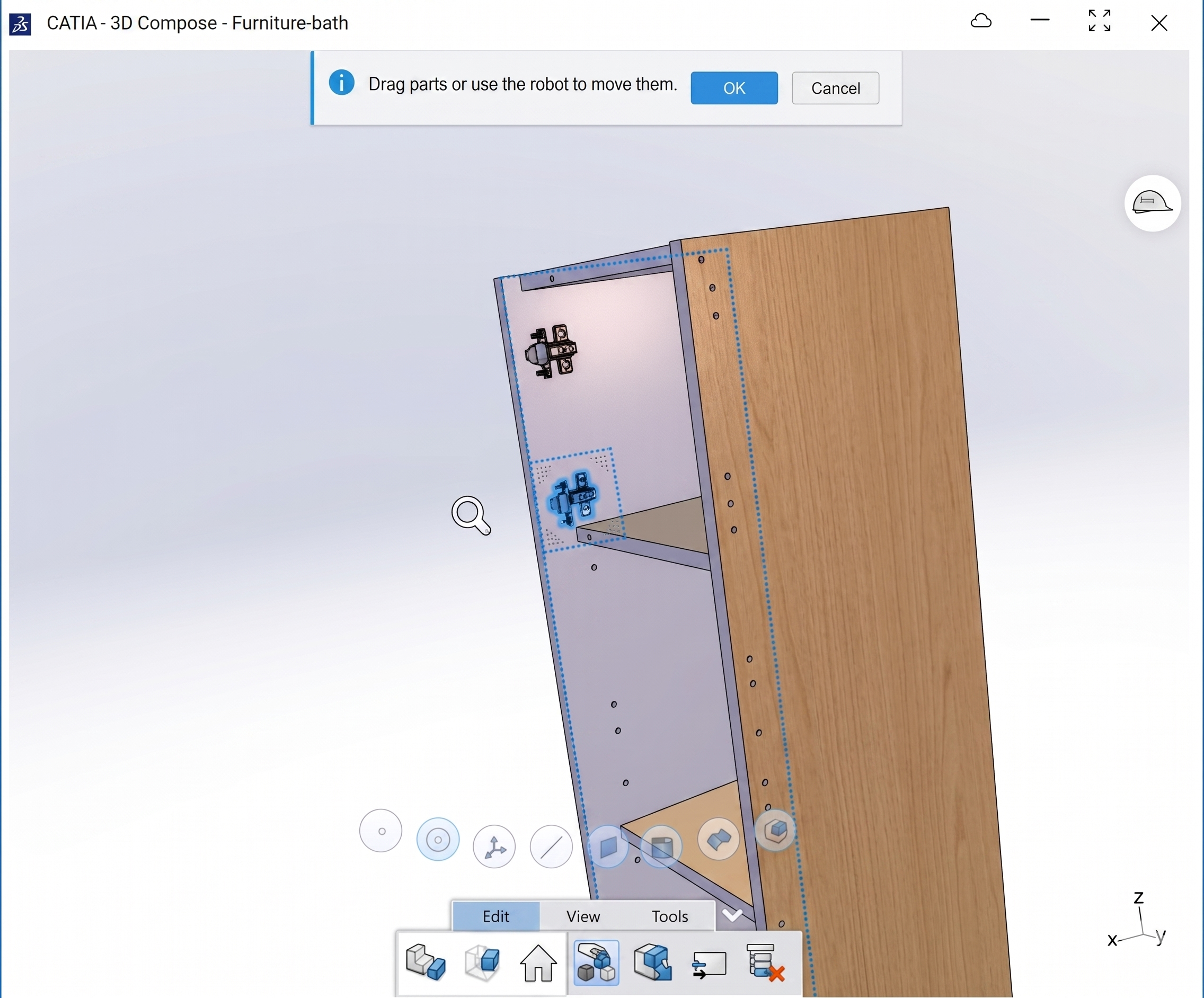
Fig: Assembling the Components


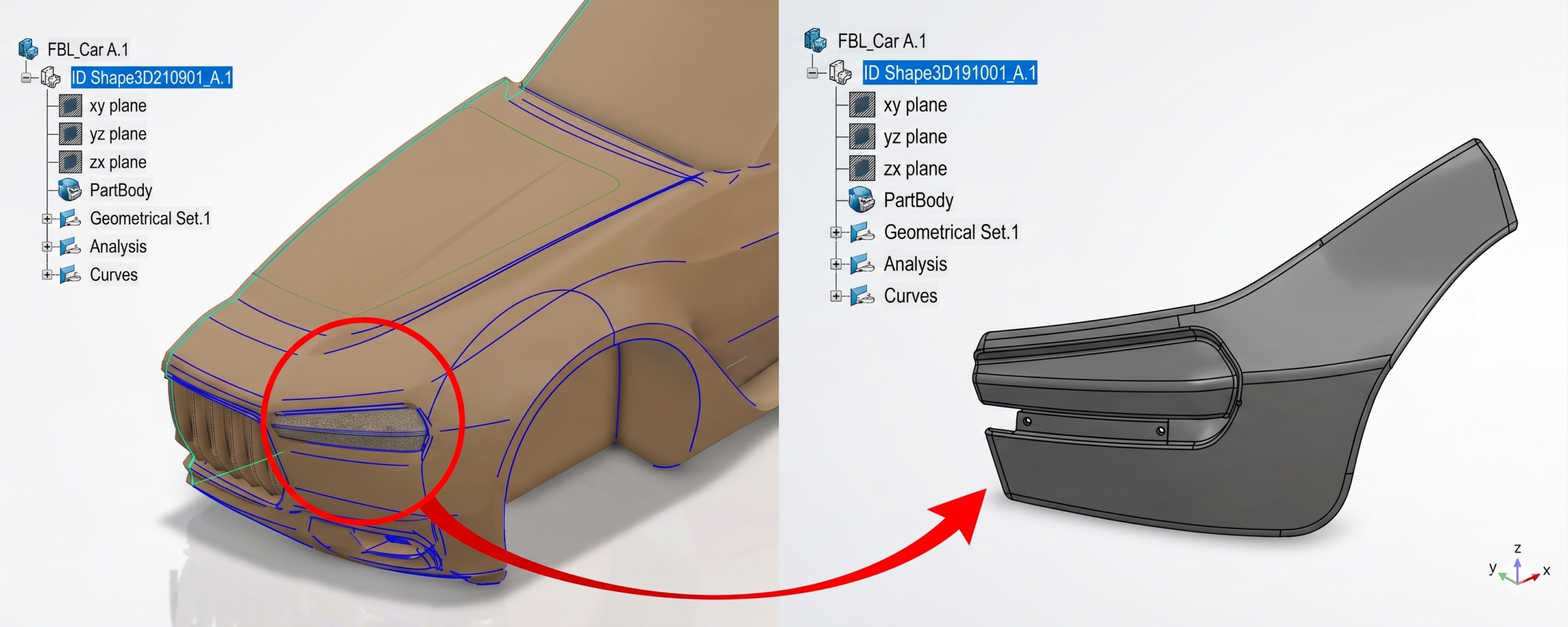
One of the most powerful capabilities of this role is the creation of detailed 3D illustrated views. These include exploded views that clearly show how parts are assembled or disassembled, making them especially useful for maintenance manuals and assembly instructions. Additional enhancements, often referred to as “dress-up,” allow illustrators to apply colors, annotations, callouts, and highlights to emphasize critical components or steps. This significantly improves clarity and usability for technicians and end users.


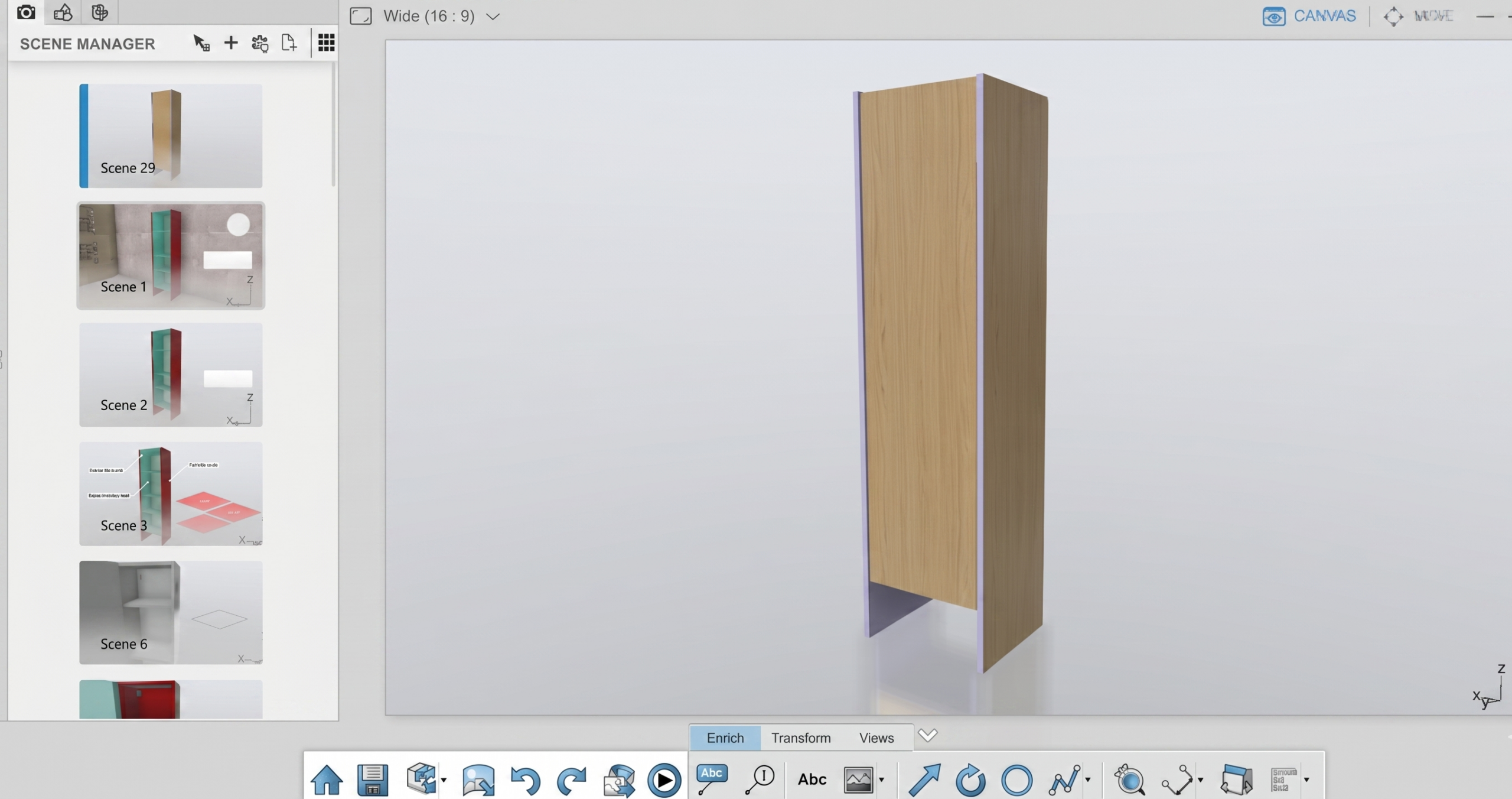
Fig: Creating Scenes for of the product showing different scenarios


Beyond static visuals, the 3D Technical Illustrator supports the generation of both 2D and 3D outputs. High-quality raster and vector images can be produced and published directly to collaborative environments such as 3DDrive, 3DSpace, and Swym communities. These outputs are essential for creating technical publications like user manuals, service guides, and installation documents. Because they are derived from the 3D model, they maintain a high level of accuracy and visual consistency.


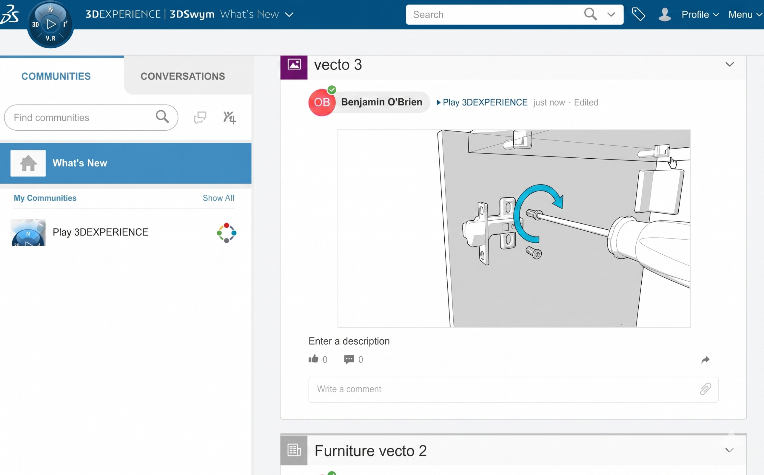
Fig: Posting the created 3D Technical Illustration on Swym community


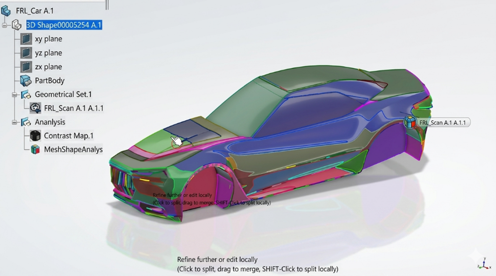
In addition to traditional documentation, the role enables the creation of immersive 3D interactive experiences. These experiences allow users to explore products dynamically—rotating, zooming, and interacting with components to better understand functionality and assembly sequences. This is particularly valuable in industries such as automotive, aerospace, and industrial equipment, where visual comprehension can significantly improve efficiency and reduce errors.


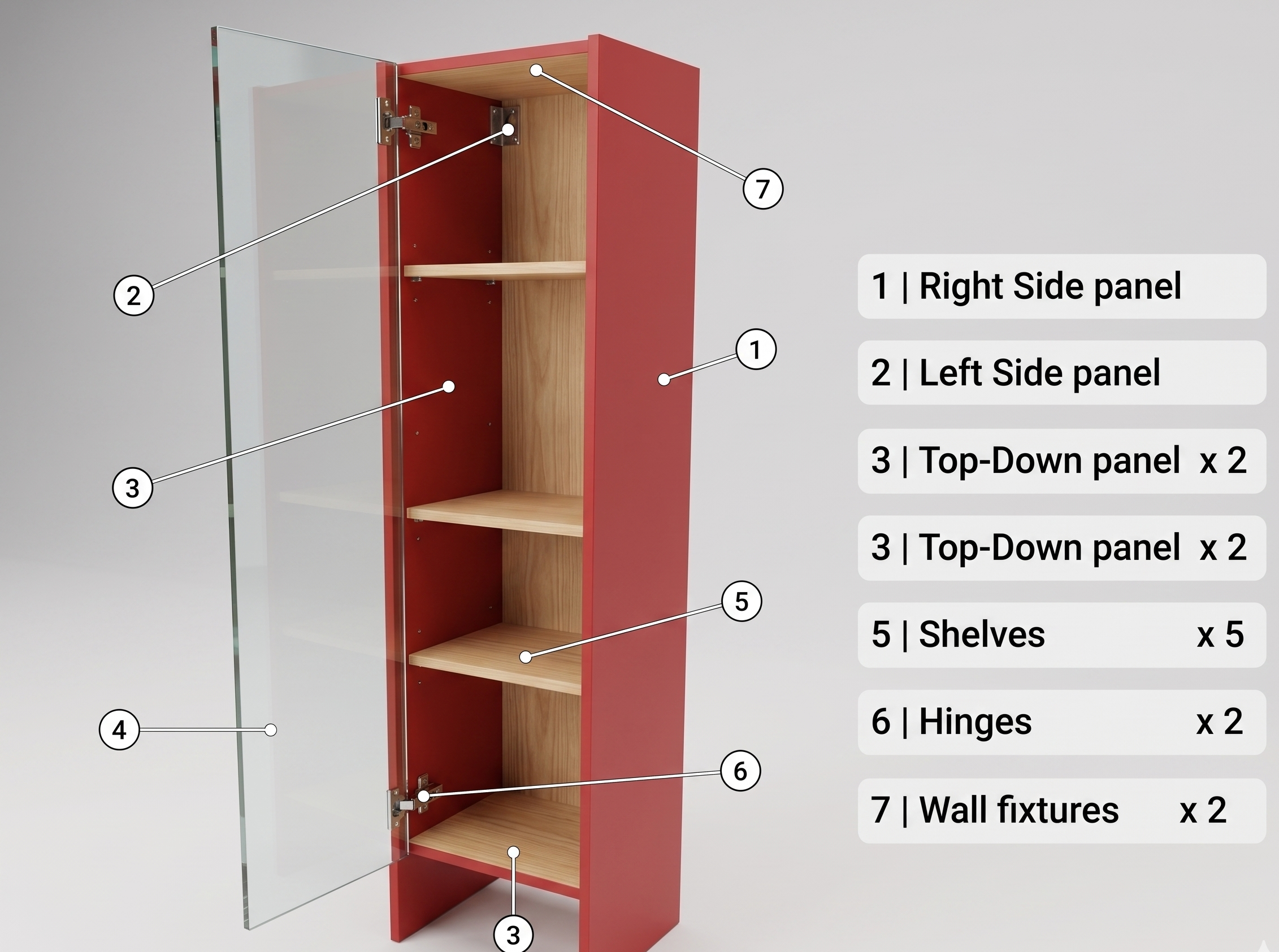
Fig: Creating the annotations of the product


Another key capability is the production of video outputs. Animated sequences can demonstrate assembly procedures, maintenance workflows, or operational instructions in a step-by-step format. Compared to static manuals, these videos provide a more engaging and intuitive way to communicate complex processes, reducing training time and improving knowledge retention.

Fig: Product with background scenes as a bathroom furniture


The benefits of adopting the 3D Technical Illustrator role are substantial. Organizations can streamline the creation of technical documentation, reduce dependency on manual drafting, and ensure that all outputs are synchronized with the latest design data. This leads to faster documentation cycles, improved accuracy, and enhanced collaboration across teams. Moreover, the ability to deliver content anytime, anywhere, and on any device aligns with modern digital transformation goals.


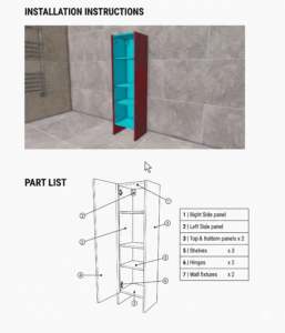
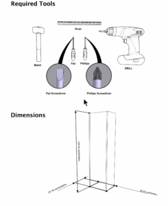
Fig: Technical Document created using 3D Technical Illustrator


In summary, the 3D Technical Illustrator role is a powerful extension of the digital engineering ecosystem. It transforms product data into meaningful technical communication assets, supporting everything from assembly instructions to interactive training materials. By integrating design, visualization, and collaboration within a unified platform, it enables organizations to deliver high-quality technical documentation that meets the demands of today’s complex product environments.

Transforming Physical Parts into Digital Models with CATIA 3DEXPERIENCE Reverse Engineer role

Reverse engineering has become a critical capability in modern product development, especially when working with legacy components, competitor benchmarking, or physical prototypes that lack digital design data. Within the CATIA 3DEXPERIENCE ecosystem, reverse engineering is not just about recreating geometry—it is about transforming real-world data into intelligent, parametric, and fully associative models that can be reused across the product lifecycle.

At its core, reverse engineering in CATIA 3DEXPERIENCE begins with data acquisition. Physical parts are typically scanned using 3D scanning technologies such as laser scanners or structured light scanners, producing dense point clouds or mesh data (STL format). These raw datasets often contain noise, irregularities, and gaps. The platform provides robust tools to clean and optimize this scan data, ensuring accuracy before moving to the modelling phase. This preprocessing step is crucial because the quality of the final CAD model heavily depends on how well the scan data is refined.

Fig 1: Reverse Engineering Workflow: From Scan to CAD


Once the scan data is prepared, CATIA 3DEXPERIENCE offers specialized roles such as Digitized Shape Preparation (DSP) and Digitized Shape Editor (DSE) to convert mesh data into usable surfaces. Engineers can segment the mesh, extract key features, and identify geometric patterns such as planes, cylinders, and freeform surfaces. This step bridges the gap between unstructured scan data and structured CAD geometry. Unlike traditional CAD modelling, where design intent is predefined, reverse engineering requires the engineer to interpret and reconstruct the design intent from the physical model.

Fig 2: Imported Scanned data into 3DEXPERIENCE


A major advantage of reverse engineering in CATIA 3DEXPERIENCE is its ability to create parametric and feature-based models from scan data. Using advanced surfacing tools available in Generative Shape Design (GSD) and Freestyle workbenches, users can rebuild complex geometries with high precision. This is particularly useful in industries like automotive BIW (Body in White), where surface continuity (G2/G3) and accuracy are critical. The resulting model is not just a static representation—it is fully editable, allowing engineers to modify dimensions, apply constraints, and integrate it into assemblies.


Fig 3: Creating curves and converting to Surfaces


Reverse engineering also plays a vital role in inspection and validation. By comparing the reconstructed CAD model with the original scan data, engineers can perform deviation analysis to identify manufacturing defects or wear and tear. CATIA’s integration with inspection tools enables color mapping and tolerance analysis, ensuring that the recreated model meets required specifications. This is especially valuable in quality control and remanufacturing scenarios.

Fig 4: Mesh Shape Analysis showing colors based on topology.


From a collaborative standpoint, the 3DEXPERIENCE platform enhances reverse engineering workflows by enabling cloud-based data management and real-time collaboration. Teams can access scan data, CAD models, and analysis results in a unified environment, eliminating data silos. Integration with other roles across design, simulation, and manufacturing ensures that reverse-engineered models can seamlessly transition into downstream processes.

However, reverse engineering is not without challenges. Handling large scan datasets can be computationally intensive, requiring optimized hardware and data management strategies. Additionally, interpreting design intent from organic or highly complex shapes demands both technical expertise and domain knowledge. Despite these challenges, the capabilities offered by CATIA 3DEXPERIENCE significantly streamline the process and improve accuracy.

Fig 5: Final Product after Reverse Engineering


In conclusion, reverse engineering in CATIA 3DEXPERIENCE is a powerful enabler for innovation, especially in scenarios where original design data is unavailable. By combining advanced scanning integration, robust surfacing tools, parametric modelling, and knowledge-based automation, the platform transforms physical components into intelligent digital assets. For engineers working in domains like automotive tooling, aerospace, and industrial equipment, mastering reverse engineering in CATIA 3DEXPERIENCE can unlock new levels of efficiency, flexibility, and competitive advantage.


Subscribe to our newsletter

Get all the latest information on Events, Sales and Offers.