Identify Stray Light in Imaging Systems with LightTools

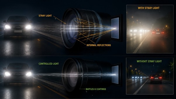
Stray light is undesired light radiation that interacts with the components of a system and degrades its performance by generating noise, that significantly reduces image quality and affects accuracy. These unintended reflections or scattering of light can be either from the object that the optical system is capturing or external emitters such as the sun or moon in case of cameras and telescopes.

Stray light could distort colours, prevent detection, affect contrast and data readability that tend to severely impact safety and efficiency. For example, the ADAS system in vehicles rely on multiple cameras for detection but the headlamps of on-coming traffic could affect the visual information being processed. Similarly, in medical imaging systems poor contrast and distortion could affect accurate diagnosis and treatment.

Fig.1. Examples of flare and ghost images in photos taken with a camera

To limit undesirable light reflections to a minimum, baffles, stop surfaces, or surface treatment/anti-reflective coatings can be used. However, the first step is to identify the source of stray light and examine the optical paths that create it.

Engineers can leverage LightTools optical design engineering software to accurately model the real-world performance of such systems and address stray light effects at the design stage itself, thus reducing multiple iterations and increasing efficiency.


LightTools Workflow For Stray Light Analysis

The aim is to examine the impact of reflections from lens surface and identify its optical path.

  • Open or import the lens model into LightTools. Align the geometry according to the global axis system and ensure all lens surfaces are grouped together and named sequentially.
  • Assign material properties to all components of the system, including lens, mirrors, baffles, mechanical mounts from the material library.
  • Choose optical property for the lens surfaces and the ray trace method. This defines if the surfaces will be reflecting, transmitting or has probabilistic ray split with Fresnel loss
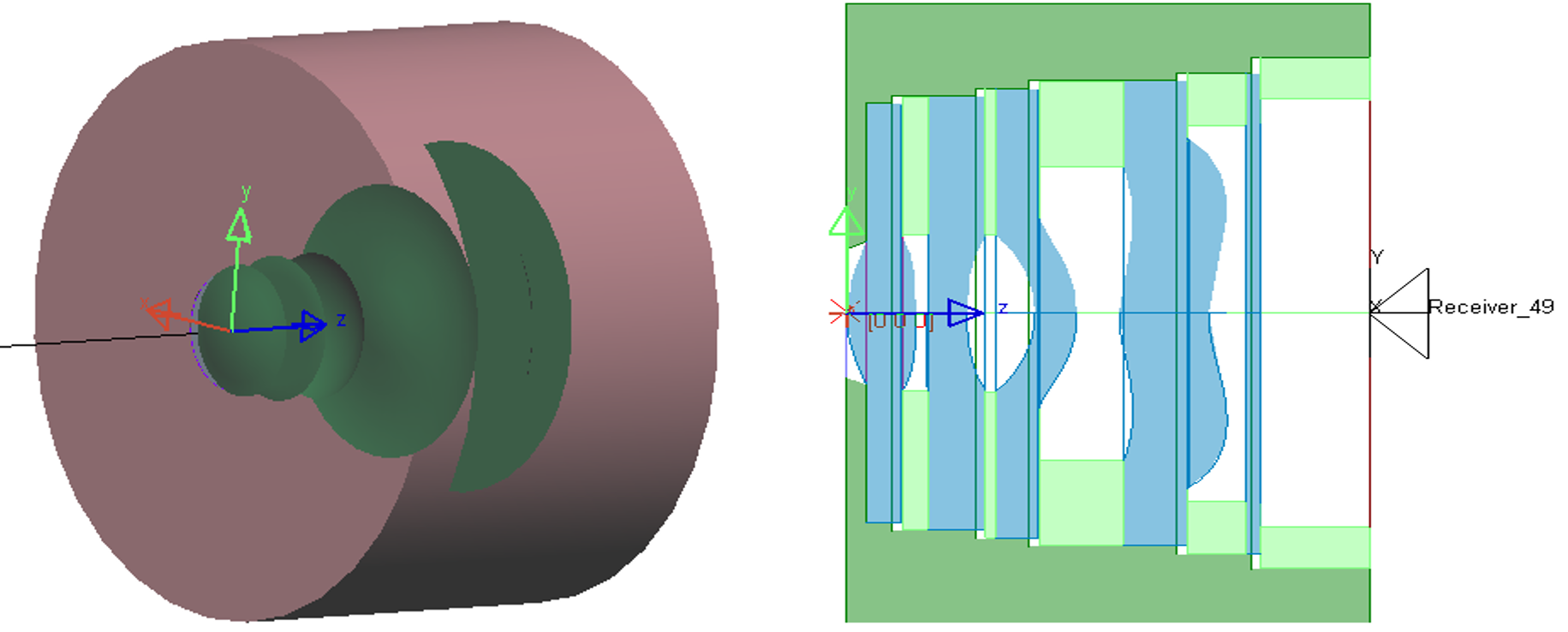
Fig.2. geometry of lens system in LightTools and its wireframe section view

  • Multiple configurations with varying optical /material properties or any independent input variable can be created at once. This helps to evaluate more than one design concept simultaneously without needing to create the model from scratch.
  • Define an object source, this could simply be a rectangular plane source the size of the image or the actual image itself can be used as a source with the image processor utility.
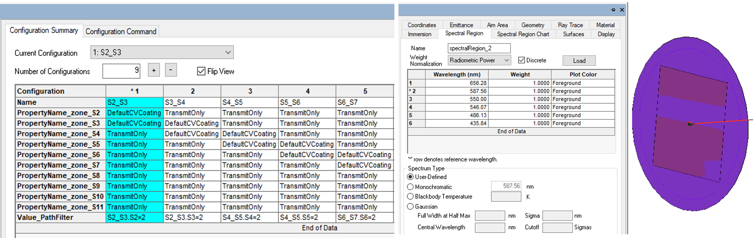
Fig.3. define multiple configurations simultaneously(left) and a plane light source creation (right)

  • Multiple configurations with varying optical /material properties or any independent input variable can be created at once. This helps to evaluate more than one design concept simultaneously without needing to create the model from scratch.
  • Define an object source, this could simply be a rectangular plane source the size of the image or the actual image itself can be used as a source with the image processor utility.
  • Add receiver filter to the exit surface and input the ray trace parameters to run the simulation. Check the ray path collection is enabled for the receiver as this will record the complete data for each optical path traced through the system. Run the Monte-Carlo ray trace.
  • Analyse the Illuminance patterns for each configuration interactively or using the parameter analyser. The ray paths traversed through the system and its corresponding illumination pattern could be visualized individually using the Ray Path tool.
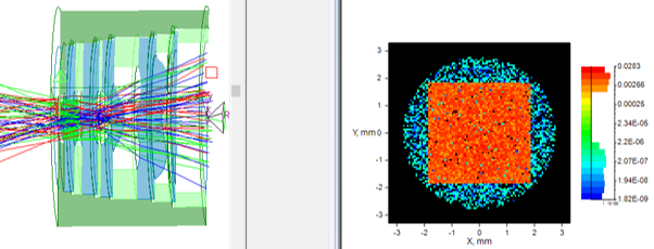
Fig.4. Visualizing rays traced through the system using Ray Path tool and its corresponding illuminance pattern
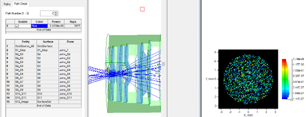
Fig.5. Ray path causing double reflections, path details and the corresponding stray light illuminance pattern produced


The tool provides complete data about the sequence of surfaces the rays are traced through and the total power, along with the illuminance pattern.

It assists engineers in detecting direct and single-bounce reflections from optical and mechanical surfaces, as well as where the ghost images will land, their size, and brightness, dependent on the geometry and coatings of each optical surface. Identifying the worst reflection pairs will help tweak the surface to reduce impact on final image.

By integrating Keysight LightTools into your early-stage workflow, you can proactively eliminate critical stray light and ghosting issues before they reach production
Redefining the Riding Experience with RAMSIS

In two‑wheeler design, comfort and safety start with the rider. RAMSIS (Realistic Anthropometric Mathematical System of Interior Comfort Simulation) is an ergonomic simulation platform that brings precise human modeling into the development of motorbikes and scooters. By combining large anthropometric databases, posture modeling, vision analysis, and reachability studies, RAMSIS lets designers evaluate how real people of different sizes interact with a vehicle long before any physical prototype exists.


Why Ergonomics And Anthropometry Matter For Two‑Wheelers

Ergonomics optimizes the fit between rider and machine; anthropometry supplies the measurements of human bodies. For two‑wheelers, small changes to handlebar height, seat shape, footpeg position, or mirror placement can dramatically affect comfort, fatigue, visibility, and control. Using anthropometric-driven simulation reduces costly late design changes and improves rider satisfaction across diverse populations.

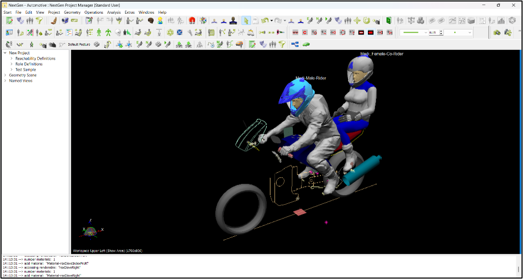
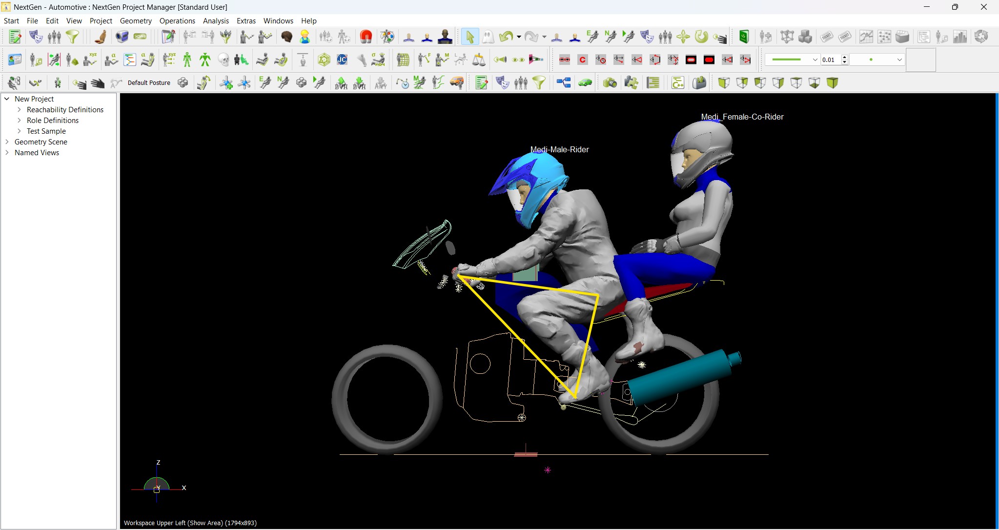
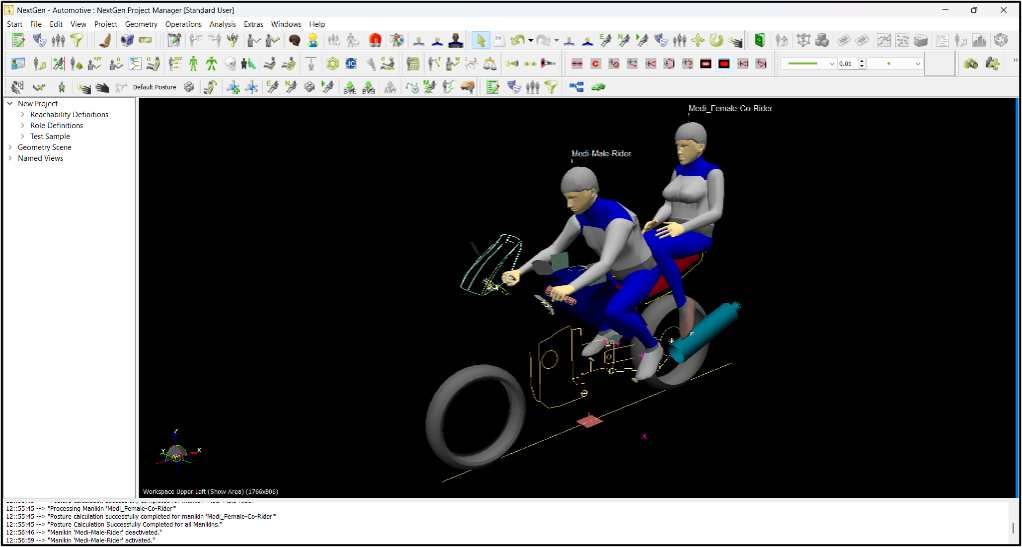
Fig 1: Shows Male Rider (50th percentile) and Female Pillion (50th percentile) withing RAMSIS standalone environment

Fig 2: Shows Male Rider (50th percentile) and Female Pillion (50th percentile) withing RAMSIS standalone environment wearing Riding gears (RAMSIS equipment Library)

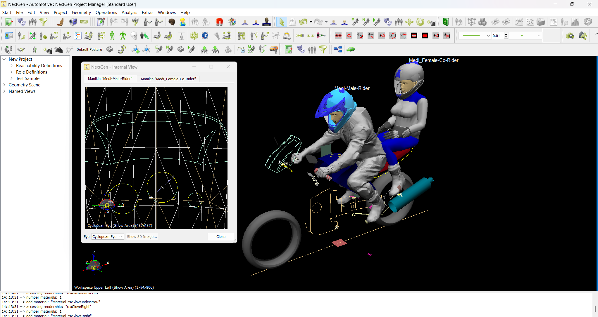
Fig 3: 50th Female Pillion Eye Vision

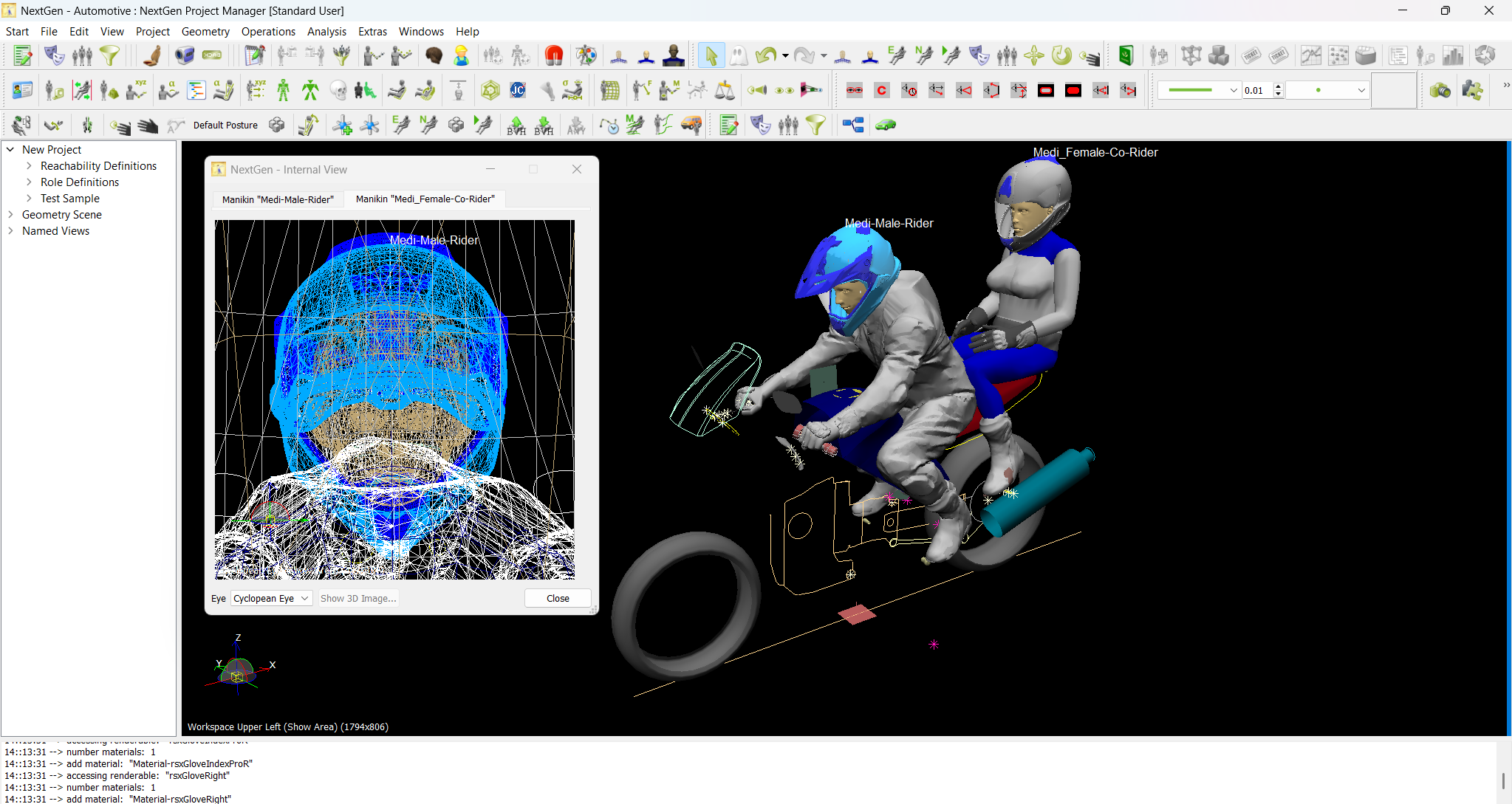
Fig 4: 50th Male Rider Eye Vision


Key RAMSIS Capabilities For Two‑Wheelers

  • Comprehensive anthropometric databases: Models draw from worldwide datasets (Germany, Japan/Korea, China, USA NHANES, India, Canada/LISA, Mexico, South America, France, and more) so designers test for regional body-size differences and global markets.
  • Automated posturing: Realistic rider postures for typical use (e.g., aggressive motorbike stance, upright scooter stance) are generated automatically to reflect natural seated positions.
  • Ground reachability analysis: Verifies whether riders of varying heights can plant feet safely when stopped, a critical safety and comfort metric for bikes and scooters.
  • Joint capacity and maximum force analysis: Assesses whether required steering, braking, or shifting forces exceed the comfort or strength limits of target user groups.
  • Vision and mirror analysis: Simulates sightlines and mirror fields to minimize blind spots and optimize mirror placement for both urban scooters and high‑speed bikes.
  • Rider triangle evaluation: Tests ergonomic relationships between seat, handlebars, and foot controls to ensure intuitive control and reduced rider strain.
  • Seat–manikin contact contour analysis: Visualizes contact between rider and seat to guide foam, shape, and contour design for long‑ride comfort.

Practical Applications In Motorbike And Scooter Development

  • Concept validation: Early-stage concepts can be checked for reach, posture, and visibility across percentile riders, avoiding costly rework.
  • Regional model tuning: Use region‑specific datasets (for example, Size India or Size North America) to tune geometry for local markets—seat height, peg position, and handlebar reach can be optimized per market.
  • Variant and accessory design: Test effects of different seats, windscreens, luggage racks, and handlebar risers on ergonomics before production.
  • Safety and usability testing: Evaluate emergency reach, mirror effectiveness, and steering forces to improve both comfort and crash preparedness.
  • Rider segmentation: Create target rider personas (commuter scooter rider, sport motorbike rider, touring rider) and tailor geometry and controls.

Example:
Designing a commuter scooter for India
Using India anthropometric data, designers run RAMSIS simulations to ensure shorter‑leg riders can still reach the ground comfortably, while also checking vision lines for typical urban traffic. Seat contour analysis helps shape a seat that reduces pressure points on long commutes. Results guide adjustments to seat height, floorboard shape, and mirror configuration before building prototypes.


Why OEMs And Designers Adopt RAMSIS

  • Faster, evidence‑based decisions that reduce physical prototyping.
  • Better market fit by validating designs for the demographics who will actually ride the product.
  • Improved rider comfort, safety, and satisfaction—key differentiators in competitive two‑wheeler markets.

Conclusion

RAMSIS turns anthropometry and ergonomics into actionable design intelligence. For motorbike and scooter manufacturers aiming to deliver comfort, control, and market‑fit, it’s a powerful tool to move from guesswork to human‑centred design.

Subscribe to our newsletter

Get all the latest information on Events, Sales and Offers.