Design Considerations during Design of Plastic Parts

- Satya Ranjan Dolai
- November 28, 2020
Plastic part design consideration plays a significant role in designing and manufacturing a plastic component. Whenever a Product Designer designs a plastic part, it is important to take care of factors such as the moulding process, selection of material, mass manufacturing process and overall area of the part around the functional need by keeping the design intent intact or the end use in consideration.
Overall Area of the Part
While engineering plastics are used in many diverse and demanding applications, the most common design elements or features influencing the overall area includes wall thickness and radius, ribs, bosses, draft etc.
-
-
- Wall thickness and radius: Wall thickness strongly influences many key part characteristics including mechanical performance, appearance, moldability and durability. So, to work with wall thickness, instead of increasing the entire wall thickness, the designer can check whether any kind of ribs, corrugations or curves can be added to get the same strength in the part as with increased wall thickness, as it leads to more weight and less moldability. By providing radius for each element instead of sharp edges, part ejection becomes easier during moulding process. Sharp edges create wear and tear which may result in malfunctioning of the final component after repeated use. The designer can then do a stiffness analysis from Analysis section before finalizing the product design.
-
-
-
- Ribs and Core Out: In case of rib design, the designer needs to take care of rib thickness. Typically, for a plastic part, rib thickness should be approx. 70% of wall thickness. Along with this, draft and edge radius should also be included. Meanwhile, if there is a complete solid area, the designer can check whether any core out is possible or not as core out gives better manufacturability maintaining right thickness, order and material flow to avoid multiple defects like sink mark, bubbles, fins etc.
-
-
-
- Bosses and Gussets: For boss design, the most important factor is to plan for the right diameter. As a thumb rule, the outside diameter should be 2 times the inside diameter. Meanwhile, if some bosses need to be placed in flange wall or at an increased height, coring out is the better design practice as it helps to reduce flow hesitation of material during moulding process. Gussets are similar to features boss with an additional stiffener. During design of Gussets, designer needs to take care of the design and ensure that no air traps and material filling arises. Refer below image for the same.
-
-
-
- Draft: Draft is the most important feature in plastic design. The purpose of providing angles or tapered face by draft is to remove the part from the mould with ease so that it is parallel to the direction of mould release. As a standard, one degree of draft is applied with additional one degree of draft for every 0.0254 mm of texture depth.
-
The above characteristics are pretty basic consideration for all kinds of plastic design components. In addition to the above characteristics, the designer should always take into consideration the undercuts, sharp corners, core creations etc.
Moulding Process
Plastic moulding is the process of pouring liquid plastic into a mould so that after a specific time, it solidifies in accordance with the provided design shape or customized shape. There are multiple types of moulding processes like extrusion moulding, blow moulding, injection moulding, rotational moulding and compression moulding.
-
-
- Extrusion moulding: In extrusion moulding, hot melted plastic is extruded and pressed through compressed air to get the desired shape. When using this process, the product will continuously have the same shape along the length.
-
-
-
- Injection moulding: This type of moulding is widely used in the industry. In this process, melted plastic is injected into a designed mould by applying high pressure. Injection moulding is often used for mass production with high levels of accuracy.
-
-
-
- Blow moulding: With blow moulding, the accuracy level of the finished component is less and thin walled. In this process, air pressure is applied inside the mould to achieve the desired shape.
-
Selection of Material
In plastic design, material selection is a very important factor. For material selection, one needs to consider application of the part. For example, if in the application area, there is some thermal stress to withstand or some kind of impact to be tolerated, then for those areas material needs to be selected as per that particular requirement.
Mass Manufacturing Process
Defining the right manufacturing method can help in mass manufacturing right quality products which is the final goal for any manufacturer. Here, these two aspects design for manufacturability and design for assembly comes in. This helps to identify the right assembly process – whether the assembly will be done by fitment process or by pressed process.
Parting Line
Defining parting line while designing a part is crucial as this parting line defines the area where the mould in halves during moulding process. Multiple aspects need to be taken care like draft angle, material roughness, any surface finish etc. CATIA has Draft Analysis feature which helps the designer to ensure sufficient draft angle is provided.
CATIA Integration – Analysis
Product iteration is very expensive and time consuming for an injection manufacturing process. In case structural, stiffness or curvature analysis need to be checked, they can be easily done using engineering simulation applications. CATIA Analysis for Designers is one such application which the designer can readily use to check for validating these aspects.
Industry Pain Areas
Most of the plastic product manufacturing organizations face multiple problems during manufacturing. Some common challenges faced by plastic manufacturing organizations are:
-
- When a part is to be ejected against the draft direction – in such cases, the designer must be aware of manufacturing constraints and the quantum of force ejection that can be done.
- When there are multiple no. of lifter or slider arrangements – in such cases, tool designer must analyse the slider movement with respect to time taking into consideration the cooling time. So, in those cases, CATIA Mould Tooling workbench can really be helpful.
- When designer reverse engineers a product – in such cases, achieving the desired parameter in terms of performance is a challenging task. This can be mitigated by simulating the results through virtual analysis.
- Assembly of rubber part and plastic part – for a leak proof product, the designer should not prefer the parting line as it creates material flushes in those particular junctions and it results in leakage as well as breakage or tear of rubber parts from inner surface. All these challenges can be addressed beforehand by analysing the parting line position and by doing a mock up.
Recent Posts
-
From Prototypes to Production: How Additive Manufacturing is Shaping Atmanirbhar Bharat
The conversation around additive manufacturing (AM) in India has evolved considerably over the past decade. What was once viewed primarily as a prototyping technology is…
-
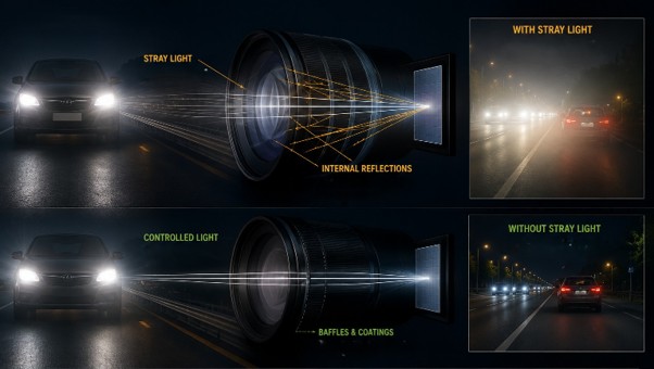
Identify Stray Light in Imaging Systems with LightTools
Stray light is undesired light radiation that interacts with the components of a system and degrades its performance by generating noise, that significantly reduces image…
-
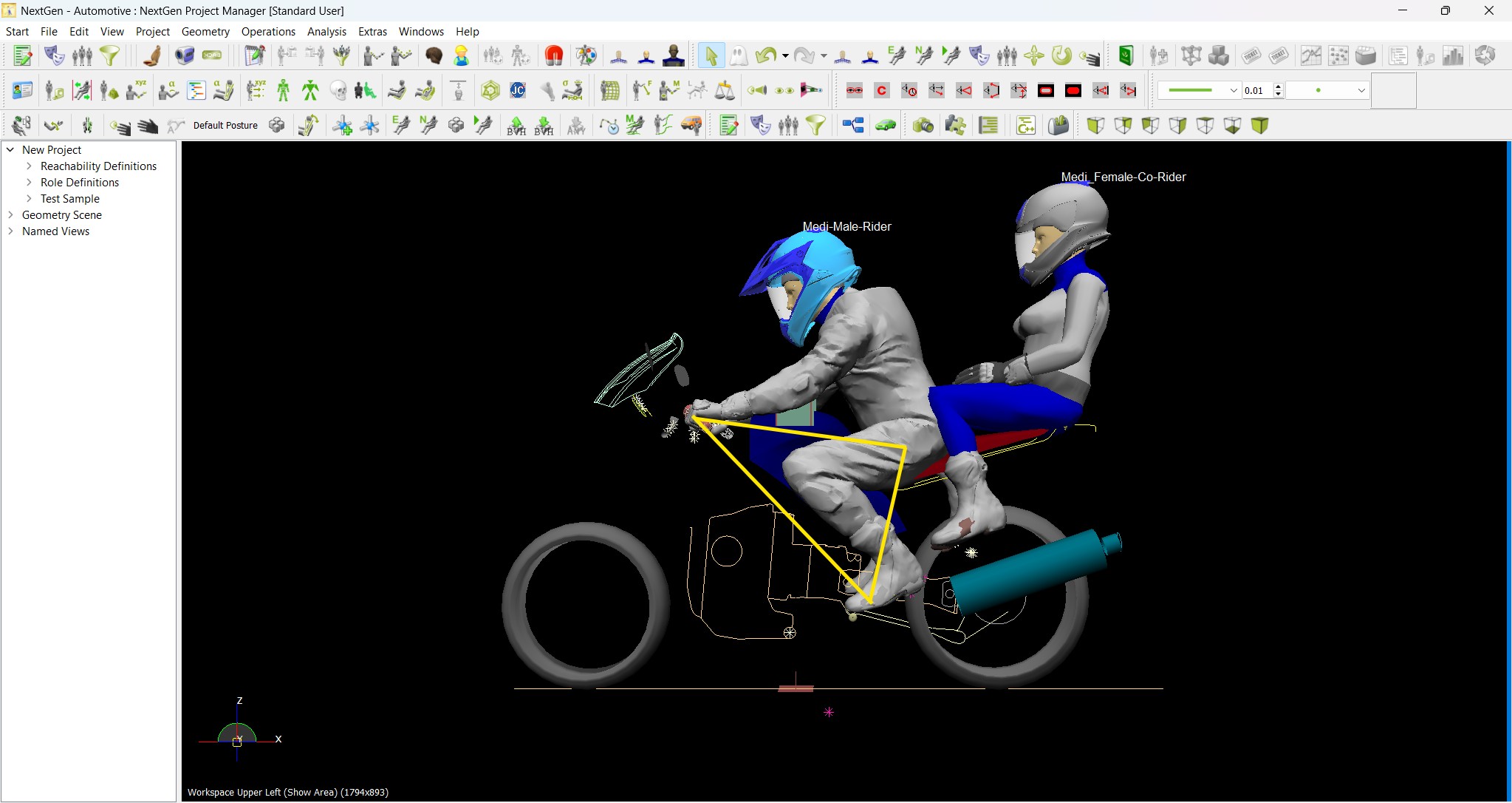
Redefining the Riding Experience with RAMSIS
In two‑wheeler design, comfort and safety start with the rider. RAMSIS (Realistic Anthropometric Mathematical System of Interior Comfort Simulation) is an ergonomic simulation platform that…
-
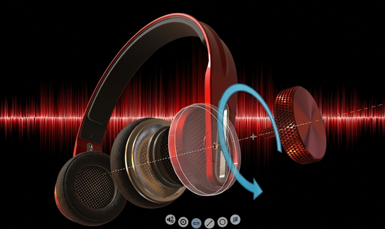
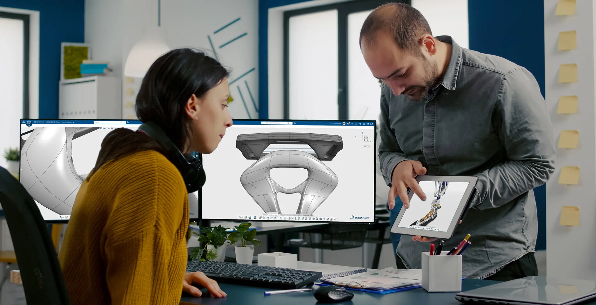
Enhancing Product Understanding through 3D Technical Illustrator
The 3D Technical Illustrator role within the 3DEXPERIENCE Platform enables organizations to transform complex engineering data into clear, interactive, and visually rich technical documentation. In…
-
Transforming Physical Parts into Digital Models with CATIA 3DEXPERIENCE Reverse Engineer role
Reverse engineering has become a critical capability in modern product development, especially when working with legacy components, competitor benchmarking, or physical prototypes that lack digital…
-
Fixing Search Service Down Issue in 3DEXPERIENCE Platform
Search is one of the most critical features in the 3DEXPERIENCE platform. If the search service goes down, users cannot find objects, documents, or data—impacting…
-
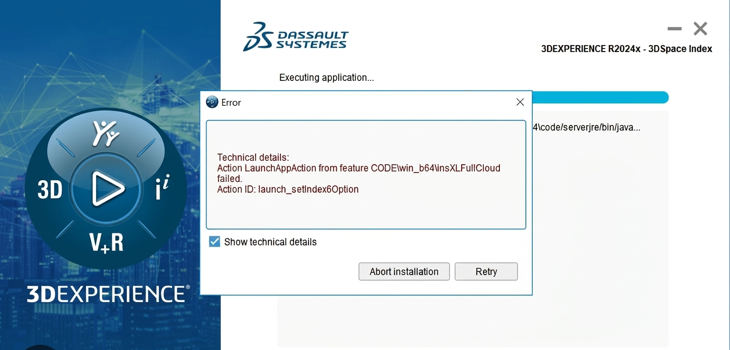
Common Installation Errors and How to Fix Them in 3DEXPERIENCE
The 3DEXPERIENCE Platform is a powerful solution used by industries worldwide for product lifecycle management (PLM), simulation, and collaboration. However, installing 3DEXPERIENCE—especially on-premise—can be complex…
-
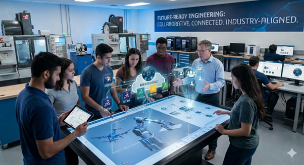
From Classroom to Industry: Empowering Future Engineers with the 3DEXPERIENCE Platform
In today’s fast-evolving engineering and design landscape, educational institutions must go beyond conventional CAD teaching methods. While standalone tools like CATIA V5, SOLIDWORKS, or traditional…
- Satya Ranjan Dolai
- November 28, 2020
Design Considerations during Design of Plastic Parts
Plastic part design consideration plays a significant role in designing and manufacturing a plastic component. Whenever a Product Designer designs a plastic part, it is important to take care of factors such as the moulding process, selection of material, mass manufacturing process and overall area of the part around the functional need by keeping the design intent intact or the end use in consideration.
Overall Area of the Part
While engineering plastics are used in many diverse and demanding applications, the most common design elements or features influencing the overall area includes wall thickness and radius, ribs, bosses, draft etc.
-
-
- Wall thickness and radius: Wall thickness strongly influences many key part characteristics including mechanical performance, appearance, moldability and durability. So, to work with wall thickness, instead of increasing the entire wall thickness, the designer can check whether any kind of ribs, corrugations or curves can be added to get the same strength in the part as with increased wall thickness, as it leads to more weight and less moldability. By providing radius for each element instead of sharp edges, part ejection becomes easier during moulding process. Sharp edges create wear and tear which may result in malfunctioning of the final component after repeated use. The designer can then do a stiffness analysis from Analysis section before finalizing the product design.
-
-
-
- Ribs and Core Out: In case of rib design, the designer needs to take care of rib thickness. Typically, for a plastic part, rib thickness should be approx. 70% of wall thickness. Along with this, draft and edge radius should also be included. Meanwhile, if there is a complete solid area, the designer can check whether any core out is possible or not as core out gives better manufacturability maintaining right thickness, order and material flow to avoid multiple defects like sink mark, bubbles, fins etc.
-
-
-
- Bosses and Gussets: For boss design, the most important factor is to plan for the right diameter. As a thumb rule, the outside diameter should be 2 times the inside diameter. Meanwhile, if some bosses need to be placed in flange wall or at an increased height, coring out is the better design practice as it helps to reduce flow hesitation of material during moulding process. Gussets are similar to features boss with an additional stiffener. During design of Gussets, designer needs to take care of the design and ensure that no air traps and material filling arises. Refer below image for the same.
-
-
-
- Draft: Draft is the most important feature in plastic design. The purpose of providing angles or tapered face by draft is to remove the part from the mould with ease so that it is parallel to the direction of mould release. As a standard, one degree of draft is applied with additional one degree of draft for every 0.0254 mm of texture depth.
-
The above characteristics are pretty basic consideration for all kinds of plastic design components. In addition to the above characteristics, the designer should always take into consideration the undercuts, sharp corners, core creations etc.
Moulding Process
Plastic moulding is the process of pouring liquid plastic into a mould so that after a specific time, it solidifies in accordance with the provided design shape or customized shape. There are multiple types of moulding processes like extrusion moulding, blow moulding, injection moulding, rotational moulding and compression moulding.
-
-
- Extrusion moulding: In extrusion moulding, hot melted plastic is extruded and pressed through compressed air to get the desired shape. When using this process, the product will continuously have the same shape along the length.
-
-
-
- Injection moulding: This type of moulding is widely used in the industry. In this process, melted plastic is injected into a designed mould by applying high pressure. Injection moulding is often used for mass production with high levels of accuracy.
-
-
-
- Blow moulding: With blow moulding, the accuracy level of the finished component is less and thin walled. In this process, air pressure is applied inside the mould to achieve the desired shape.
-
Selection of Material
In plastic design, material selection is a very important factor. For material selection, one needs to consider application of the part. For example, if in the application area, there is some thermal stress to withstand or some kind of impact to be tolerated, then for those areas material needs to be selected as per that particular requirement.
Mass Manufacturing Process
Defining the right manufacturing method can help in mass manufacturing right quality products which is the final goal for any manufacturer. Here, these two aspects design for manufacturability and design for assembly comes in. This helps to identify the right assembly process – whether the assembly will be done by fitment process or by pressed process.
Parting Line
Defining parting line while designing a part is crucial as this parting line defines the area where the mould in halves during moulding process. Multiple aspects need to be taken care like draft angle, material roughness, any surface finish etc. CATIA has Draft Analysis feature which helps the designer to ensure sufficient draft angle is provided.
CATIA Integration – Analysis
Product iteration is very expensive and time consuming for an injection manufacturing process. In case structural, stiffness or curvature analysis need to be checked, they can be easily done using engineering simulation applications. CATIA Analysis for Designers is one such application which the designer can readily use to check for validating these aspects.
Industry Pain Areas
Most of the plastic product manufacturing organizations face multiple problems during manufacturing. Some common challenges faced by plastic manufacturing organizations are:
-
- When a part is to be ejected against the draft direction – in such cases, the designer must be aware of manufacturing constraints and the quantum of force ejection that can be done.
- When there are multiple no. of lifter or slider arrangements – in such cases, tool designer must analyse the slider movement with respect to time taking into consideration the cooling time. So, in those cases, CATIA Mould Tooling workbench can really be helpful.
- When designer reverse engineers a product – in such cases, achieving the desired parameter in terms of performance is a challenging task. This can be mitigated by simulating the results through virtual analysis.
- Assembly of rubber part and plastic part – for a leak proof product, the designer should not prefer the parting line as it creates material flushes in those particular junctions and it results in leakage as well as breakage or tear of rubber parts from inner surface. All these challenges can be addressed beforehand by analysing the parting line position and by doing a mock up.