Links Management in CATIA V5

- Mohit Aggarwal
- December 21, 2020
CATIA link is a dependency relation used to share geometric, parametric or positioning information between components in CATIA V5. Links in CATIA are unidirectional and always point from the child to the parent.
Types of Links
There are five types of links each of which are explained below with a common example.
The CCP link
The first CAT Part contains the geometrical definition of the raw material used to create the table leg. The second CAT Part contains the geometrical definition of the finished table leg. Consistency must be ensured between the models: a modification of the raw material must be reflected in the finished leg. For that purpose, the raw material part geometry is copied and pasted in the finished part (with the link maintained), where the machining operations are performed.Since the raw material and the finished leg will never be assembled together, this operation is performed outside the context of an assembly.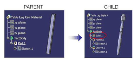
The CCP link is created in a part when the geometry is pasted using the ‘Paste special as result with link’ functionality provided the copy/paste operation is performed from part to part and outside the context of a product.
The KWE link
The leg socket is the common interface between the table leg and the tabletop. The dimensions of the socket are stored in parameters in the tabletop part. For the table leg to match the tabletop, those dimensions must match. For that purpose, the dimension can be copied (with the link maintained) from the tabletop to the table leg.
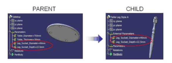
This link is in all points identical to the CCP link, except that parameters are copied instead of geometry.
The KWE link is created in a part where parameters are pasted using the ‘Paste special as result with link’ functionality.
The Instance link
To create a table assembly, the tabletop and table leg components must be inserted in the table assembly CAT Product.
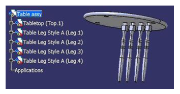
In this process, the table assembly is the parent and the tabletop and table legs are the children. In the table assembly, an Instance link is created for each component. This link carries the name and path of the files.
The Instance link is created in a CAT Product where CAT Parts or CAT Products are inserted.
The Constraints
Assembly constraints are used to position the parts of the assembly. Each leg will require an axis-to-axis coincidence and surface-to-surface contact constraints to position it.
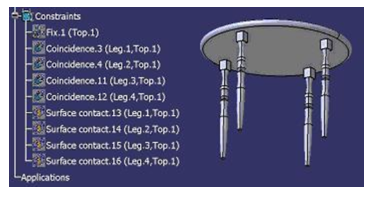
The assembly constraints allow to position parts and products in the context of an assembly. This type of link cannot be visualized in the Edit/ Links menu. The links are stored in the CATProduct and apply to the instance of the components. In other words, an assembly constraint applies to a specific representation of a part in a specific assembly. For example, if the Leg 1 instance is constrained, all the other table leg instances are still free.
If the table leg style A was replaced by a table leg style B in the table assembly, all the constraints would be broken. The use of publications prevents this behavior. If the same publication name (Leg Axis) is applied to both table legs’ axis, the assembly constraint will be reconnected automatically when the table leg is replaced with the second one.
The constraint is created between two part/ product instances. The use of publications will allow reconnecting the constraints automatically when parts are replaced.
The View Link
The table leg CAT Part contains the 3D geometrical definition and a CAT Drawing contains the associated 2D representation. The views are generated from the CAT Part using Generative Drafting functionalities. Whenever the part is modified, the drawing views indicate an update is required to reflect the changes.
This process does not create any external link in the CAT Part (the parent). In the CAT Drawing (the child), a View Link points to the CAT Part (the parent). The View Link is created for each generative view of a drawing. The information carried by the link is the name and path of the source model used for the projection.
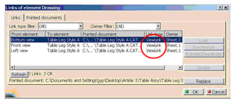
The View Link is created between the CAT Drawing for each generated view. The link points to the object used to create the view (CAT Part or CAT Product)
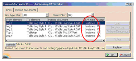
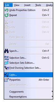
To access Links in CATIA V5, Select Edit ➜ Links.
Here, the pointed documents of Assembly, Part and Drawings can be seen.
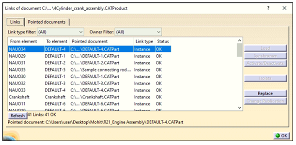
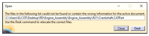
Sometimes when an assembly is opened, an error pops up displaying “File could not be found”. This error occurs when the Part or Drawing File is missing from the location it was kept earlier. This error can be resolved by selecting Desk from error message or Select File ➜ Desk.
For example, Crankshaft is the missing part in the below error message.
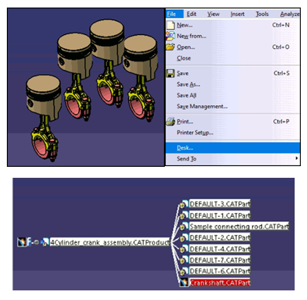
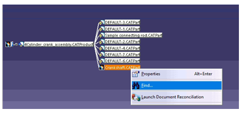
The part file which is highlighted in red color is missing. Right click on the missing part and select Find. Now browse to the path where that file is kept and select the file. The red highlighted part will turn into white color which means that the part is found and loaded in the assembly.
Recent Posts
-
Identify Stray Light in Imaging Systems with LightTools
Stray light is undesired light radiation that interacts with the components of a system and degrades its performance by generating noise, that significantly reduces image…
-
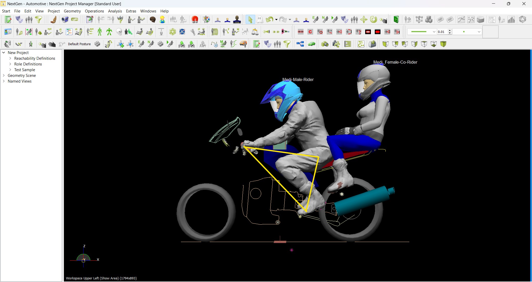
Redefining the Riding Experience with RAMSIS
In two‑wheeler design, comfort and safety start with the rider. RAMSIS (Realistic Anthropometric Mathematical System of Interior Comfort Simulation) is an ergonomic simulation platform that…
-
Enhancing Product Understanding through 3D Technical Illustrator
The 3D Technical Illustrator role within the 3DEXPERIENCE Platform enables organizations to transform complex engineering data into clear, interactive, and visually rich technical documentation. In…
-
Transforming Physical Parts into Digital Models with CATIA 3DEXPERIENCE Reverse Engineer role
Reverse engineering has become a critical capability in modern product development, especially when working with legacy components, competitor benchmarking, or physical prototypes that lack digital…
-
Fixing Search Service Down Issue in 3DEXPERIENCE Platform
Search is one of the most critical features in the 3DEXPERIENCE platform. If the search service goes down, users cannot find objects, documents, or data—impacting…
-
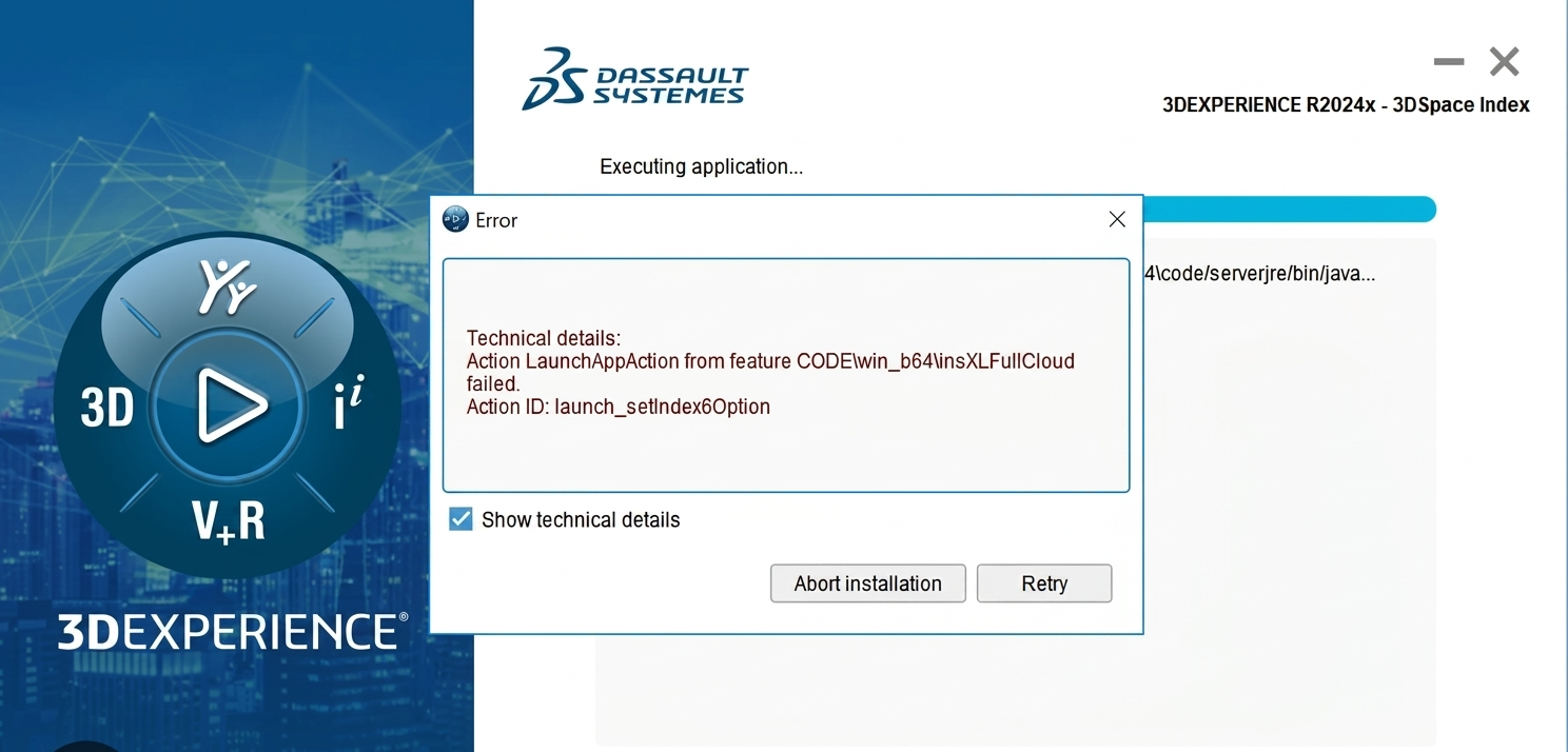
Common Installation Errors and How to Fix Them in 3DEXPERIENCE
The 3DEXPERIENCE Platform is a powerful solution used by industries worldwide for product lifecycle management (PLM), simulation, and collaboration. However, installing 3DEXPERIENCE—especially on-premise—can be complex…
-
From Classroom to Industry: Empowering Future Engineers with the 3DEXPERIENCE Platform
In today’s fast-evolving engineering and design landscape, educational institutions must go beyond conventional CAD teaching methods. While standalone tools like CATIA V5, SOLIDWORKS, or traditional…
-
CATIA Composer – Transforming Engineering Data into Interactive Technical Documentation
CATIA Composer is a powerful desktop application from Dassault Systemes designed to transform engineering 3D CAD data into highly intuitive and interactive technical documentation. In…
- Mohit Aggarwal
- December 21, 2020
Links Management in CATIA V5
CATIA link is a dependency relation used to share geometric, parametric or positioning information between components in CATIA V5. Links in CATIA are unidirectional and always point from the child to the parent.
Types of Links
There are five types of links each of which are explained below with a common example.
The CCP link
The first CAT Part contains the geometrical definition of the raw material used to create the table leg. The second CAT Part contains the geometrical definition of the finished table leg. Consistency must be ensured between the models: a modification of the raw material must be reflected in the finished leg. For that purpose, the raw material part geometry is copied and pasted in the finished part (with the link maintained), where the machining operations are performed.Since the raw material and the finished leg will never be assembled together, this operation is performed outside the context of an assembly.
The CCP link is created in a part when the geometry is pasted using the ‘Paste special as result with link’ functionality provided the copy/paste operation is performed from part to part and outside the context of a product.
The KWE link
The leg socket is the common interface between the table leg and the tabletop. The dimensions of the socket are stored in parameters in the tabletop part. For the table leg to match the tabletop, those dimensions must match. For that purpose, the dimension can be copied (with the link maintained) from the tabletop to the table leg.
This link is in all points identical to the CCP link, except that parameters are copied instead of geometry.
The KWE link is created in a part where parameters are pasted using the ‘Paste special as result with link’ functionality.
The Instance link
To create a table assembly, the tabletop and table leg components must be inserted in the table assembly CAT Product.
In this process, the table assembly is the parent and the tabletop and table legs are the children. In the table assembly, an Instance link is created for each component. This link carries the name and path of the files.
The Instance link is created in a CAT Product where CAT Parts or CAT Products are inserted.
The Constraints
Assembly constraints are used to position the parts of the assembly. Each leg will require an axis-to-axis coincidence and surface-to-surface contact constraints to position it.
The assembly constraints allow to position parts and products in the context of an assembly. This type of link cannot be visualized in the Edit/ Links menu. The links are stored in the CATProduct and apply to the instance of the components. In other words, an assembly constraint applies to a specific representation of a part in a specific assembly. For example, if the Leg 1 instance is constrained, all the other table leg instances are still free.
If the table leg style A was replaced by a table leg style B in the table assembly, all the constraints would be broken. The use of publications prevents this behavior. If the same publication name (Leg Axis) is applied to both table legs’ axis, the assembly constraint will be reconnected automatically when the table leg is replaced with the second one.
The constraint is created between two part/ product instances. The use of publications will allow reconnecting the constraints automatically when parts are replaced.
The View Link
The table leg CAT Part contains the 3D geometrical definition and a CAT Drawing contains the associated 2D representation. The views are generated from the CAT Part using Generative Drafting functionalities. Whenever the part is modified, the drawing views indicate an update is required to reflect the changes.
This process does not create any external link in the CAT Part (the parent). In the CAT Drawing (the child), a View Link points to the CAT Part (the parent). The View Link is created for each generative view of a drawing. The information carried by the link is the name and path of the source model used for the projection.
The View Link is created between the CAT Drawing for each generated view. The link points to the object used to create the view (CAT Part or CAT Product)
To access Links in CATIA V5, Select Edit ➜ Links.
Here, the pointed documents of Assembly, Part and Drawings can be seen.
Sometimes when an assembly is opened, an error pops up displaying “File could not be found”. This error occurs when the Part or Drawing File is missing from the location it was kept earlier. This error can be resolved by selecting Desk from error message or Select File ➜ Desk.
For example, Crankshaft is the missing part in the below error message.
The part file which is highlighted in red color is missing. Right click on the missing part and select Find. Now browse to the path where that file is kept and select the file. The red highlighted part will turn into white color which means that the part is found and loaded in the assembly.