Boosting Performance in Large Assembly Patterns & Drafting Views with 3DEXPERIENCE CATIA

In today’s competitive engineering world, time is money. Designers and engineers working with large assemblies – whether in aerospace, automotive or industrial machinery – often face performance bottlenecks when generating repetitive patterns or creating 2D drafting views.

Dassault Systèmes’ 3DEXPERIENCE platform offers advanced CAD capabilities, but applying the right best practices can make the difference between a slow, resource-heavy process and a smooth, efficient workflow.

This blog explores key methods to enhance Assembly Pattern performance and Drafting View generation – with practical insights on when and why to use them.


Assembly Pattern Generation: How to Work Smarter with Repetitive Designs

Assembly patterns are widely used to duplicate standard components (bolts, rivets, seats, fasteners, or modular parts) across large products. However, handling thousands of instances can easily slow down the design system.

3DEXPERIENCE offers two methods for pattern creation:


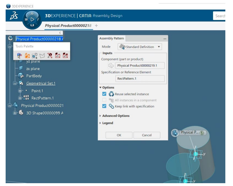
  1. Using “Keep Link with Specification” Option
  • How it works: Creates a live connection between the main part and all its patterned instances.
  • Benefit: If you modify the master part (e.g., bolt size), all instances update automatically.
  • Limitation: For very large assemblies (e.g., 1000+ parts), performance drops significantly.
  • Case Study Result:
    • Creation: ~35s
    • Update: ~17s
    • Save: ~120s
    • Modification (reduce from 1000 → 900): ~84s
    • Total Time: 256 seconds

  1. Without “Keep Link with Specification” Option
  • How it works: Instances are independent; modifying the pattern requires recreating instances.
  • Benefit: Faster performance in large assemblies where updates are rare.
  • Case Study Result:
    • Recreate pattern: ~12s
    • Update + Save: ~89s
    • Modification: ~108s
    • Total Time: 209 seconds (18% faster)

Best Practice Recommendation:

  • Use Keep Link ON → for assemblies that require frequent synchronized updates (like bolt patterns that may change size frequently).
  • Use Keep Link OFF → for very large assemblies where stability and speed are more important than live updates.

Drafting View Generation: Reducing the Wait Time

Once assemblies are complete, engineers must generate 2D drawings for manufacturing, inspection, or documentation. With thousands of parts, drafting view generation can be a time-consuming step – unless optimized.

  • Turn Off Shaded Background Mode
    • Effect: Removes unnecessary rendering of shaded views.
    • Impact: 67% faster (75s → 27s).
    • Use Case: Recommended when working with technical manufacturing drawings where hidden line views are sufficient.
  • Deactivate Clash Detection
    • Effect: Clash detection checks for interference between parts during view creation.
    • Impact: 36% faster drafting performance.
    • Use Case: Keep it OFF unless the drawing specifically requires clash validation.
  • Disable Automatic Updates
    • Effect: Creates lightweight previews first; full updates can be triggered manually or in batch mode.
    • Impact: ~33% time saving.
    • Use Case: Ideal for large assemblies where multiple views must be created quickly, and final updates can be done later.
  • Other Smart Settings
    • Occlusion Culling: Ignores parts that are not visible in the view.
    • Part Size Filter: Skips very small parts (like washers or pins) that don’t add value in drafting views.
    • Deactivate Exact Preview: Uses visualization instead of heavy geometry, improving speed.

These settings are powerful for industries like aerospace and automotive, where drawings often run into dozens of sheets and hundreds of views.


Practical Applications in Industry

  • Automotive BIW (Body-in-White):
    • Thousands of weld spots and fasteners patterned across the structure.
    • Using Keep Link OFF reduces lag while working on massive assemblies.
  • Aerospace (Aircraft Fuselage):
    • Repeated seat patterns and rivets along the fuselage.
    • Drafting optimizations cut drawing generation time for certification documents.
  • Heavy Machinery & Plant Engineering:
    • Assemblies with repetitive bolts, brackets, and structural members.
    • Smart drafting settings reduce time-to-documentation for field manuals.

Conclusion

Efficiency in CAD isn’t just about tools – it’s about using them wisely. Dassault Systèmes’ 3DEXPERIENCE platform gives engineers powerful options to handle massive assemblies, but performance depends on configuration choices:

  • For Assembly Patterns → Use Keep Link OFF for better speed in large assemblies and Keep Link ON only when synchronized updates are essential.
  • For Drafting Views → Switch OFF heavy options like Shaded Background, Clash Detection, and Auto Update to save up to 60–70% of time.

By applying these practices, companies can significantly reduce design-to-documentation cycles, enabling faster innovation, quicker manufacturing preparation, and more efficient collaboration across teams.


Reduce Errors and Repetitive Tasks with Assembly Symmetry & Pattern in 3DEXPERIENCE R2024x

In modern product development, design efficiency is not just about speed – it’s about precision, automation, and reusability. Dassault Systèmes 3DEXPERIENCE R2024x introduces advanced capabilities in Assembly Symmetry and Assembly Pattern that empower engineers to streamline repetitive design tasks, maintain associativity, and reduce errors.

These two functions – though often used together – serve distinct purposes in mechanical design. Let’s dive into how they work and why they matter.


Assembly Symmetry: Mirroring Made Smarter

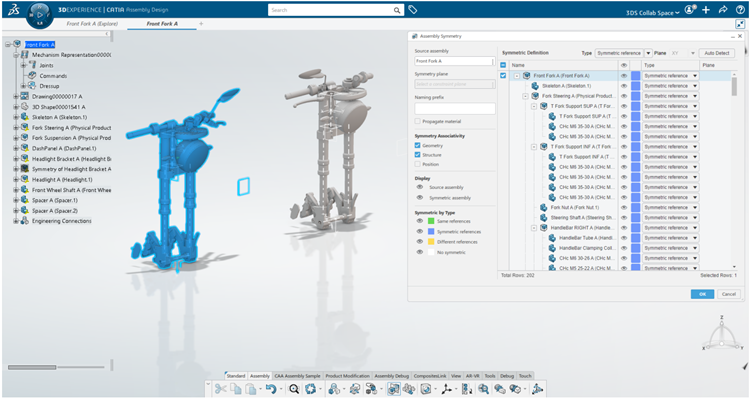
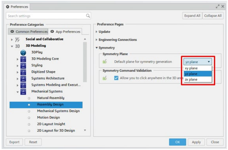
The Assembly Symmetry command allows designers to quickly generate symmetric product structures from an existing assembly. Instead of recreating mirrored components manually, the system leverages defined symmetry planes (by default YZ, but configurable to ZX or XY).

Key features include:

  • Symmetry of Root Products vs. Sub-Products – Designers can apply symmetry to the entire assembly (root) or selectively to sub-products.
  • Specification Types – Users can choose between Symmetric References, Same Reference, Different Reference, or No Symmetry depending on design needs.
  • Associativity Control – Geometry, structure, and position associativity ensure mirrored products remain linked to the original, automatically updating when changes occur.
  • Material & Naming Inheritance – Symmetric assemblies can inherit material properties and use customized prefixes for clarity.

Use Case Example: In automotive design, when creating left and right doors, Assembly Symmetry ensures that geometric modifications to one door propagate seamlessly to the other, saving time and reducing manual rework.


Assembly Pattern: Multiplying with Intelligence

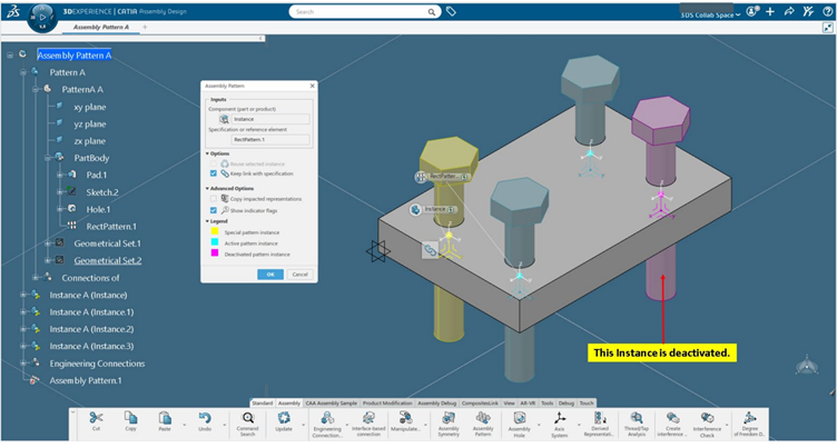
The Assembly Pattern command is designed for creating repeated instances of components within an assembly – such as bolts, rivets, or repetitive features like holes.

Supported pattern types include:

  • Rectangular Assembly Pattern
  • Circular Assembly Pattern
  • User-Defined Assembly Pattern
  • Axis System-Based Pattern
  • Patterns derived from Part Design or Generative Shape Design
  • Highlights of Assembly Pattern:
  • Associativity Options – Patterned instances remain linked to the original, so any change updates all instances.
  • Constraint Management – Engineering connections can be reused or newly assigned across instances.
  • Advanced Impact Options – Users can choose whether only clashing impacts (intersections) or all impacts are copied.
  • Visualization Tools – Color-coded legends (yellow for reference, cyan for active instances, magenta for deactivated ones) enhance clarity.

Use Case Example: In aerospace design, when placing multiple fasteners along a fuselage panel, Assembly Pattern ensures all instances follow a consistent axis system and update automatically if the base geometry changes.


Why These Functions Matter

  • Minimize repetitive manual work
  • Enhance collaboration through consistent updates
  • Reduce error risks in complex assemblies
  • Speed up design cycles in automotive, aerospace, and manufacturing industries
  • Help engineers focus on innovation rather than repetitive modeling


Conclusion

With Assembly Symmetry and Assembly Pattern, the 3DEXPERIENCE platform equips designers with automation tools that bridge creativity and efficiency. Whether mirroring large assemblies or multiplying components with precision, these features ensure that product development remains agile, reliable, and future-ready.


Simplifying Complex Automotive Meshing with Surface Wrap in 3DEXPERIENCE

In fluid simulation, especially in automotive applications, managing complex geometries like the underbody of a car can be one of the most challenging aspects of the meshing process. Small features – such as gaps between panels, minor protrusions, or tiny edge details – can significantly increase the computational complexity, time, and even lead to solver instability.

The Surface Wrap functionality in the 3DEXPERIENCE Platform – available through the SIMULIA Fluid Model Creation app – provides a powerful solution to this problem. It enables engineers to automatically seal, smooth, and simplify complicated CAD models while maintaining the essential flow paths.

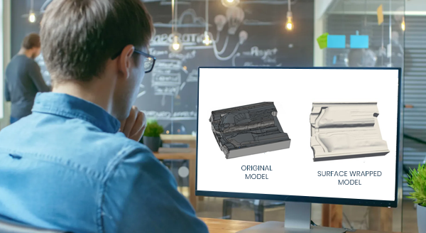
What Does the Image Show?

Left: Original car underbody with gaps and intricate features
Right: Surface-wrapped model, smoothed and meshing-ready

The image clearly demonstrates the before and after effects of surface wrapping:

  • On the left, the raw geometry contains multiple gaps, crevices, and small edges – making it difficult to generate a high-quality mesh.
  • On the right, after applying surface wrap, the same geometry is simplified and continuous, making it ideal for efficient Hex-Dominant Meshing.

This transformation is not just visual; it drastically improves mesh quality, reduces element count, and increases solver performance.


What Is Surface Wrap and Why Is It Important?

Surface Wrap is a preprocessing step that cleans up geometry by:

  • Filling small gaps between parts (e.g., < 5 mm)
  • Removing tiny, unnecessary edges and features
  • Generating a smoothed, watertight external surface
  • Enabling a robust and automated meshing process

This is especially useful in automotive CFD simulations, where:

  • Components like bonnets, pillars, and mirrors often have narrow clearances
  • Details like screws, slots, and vents don’t contribute to major flow changes
  • Full-vehicle external flow simulations demand clean geometry

Without surface wrapping, engineers would need to manually simplify geometry or spend time troubleshooting mesh failures.


Real Impact: Drastic Reduction in Mesh Complexity

Using Surface Wrap, you can reduce the mesh element count by more than 60% in many cases. For example:

  • A model with small 2 mm gaps can generate over 53,000 mesh elements.
  • When wrapped with a 3 mm wrap size, the mesh is reduced to less than 20,000 elements.

This leads to:

  • Shorter meshing time
  • Faster simulation runs
  • Fewer convergence issues


How It Works in 3DEXPERIENCE

When defining the Fluid Domain, the user simply:

  1. Enables the “Mesh with surface wrap” checkbox.
  2. Sets a minimum wrap size – usually larger than the smallest geometric gap to be ignored.
  3. Proceeds with Hex-Dominant Mesh (HDM) generation.

The software automatically:

  • Detects and seals small open edges
  • Smooths over redundant geometry
  • Generates a clean, unified surface for meshing

Once meshed, users can visualize the wrapped surface with or without edge highlighting, ensuring confidence in the final geometry.

Why It Matters

Without Surface Wrap:

  • Tiny features force finer meshes
  • Increased computation time
  • Risk of mesh failure or simulation error

With Surface Wrap:

  • Geometry is simulation-ready
  • Mesh generation is faster and cleaner
  • Better control over mesh size and quality

For automotive engineers simulating aerodynamics or underbody flow, this is a game-changing step that shifts focus from cleanup to innovation.

Conclusion

The Surface Wrap tool in the 3DEXPERIENCE Platform isn’t just a convenience – it’s a necessity for handling the complex realities of modern automotive design. Even a chaotic geometry like a car’s underbody becomes clean, streamlined, and simulation-ready with just a few intelligent preprocessing steps.

This not only saves engineering time and effort, but also boosts simulation accuracy, efficiency, and reliability. For any team working on external fluid dynamics, HVAC, or thermal management – Surface Wrap is the silent hero behind a successful CFD workflow.

Beyond the Test Track: The Virtual Leap in Automotive Lighting Assessment

The adoption of innovative technologies such as virtual reality and visual interface in the automotive sector is significantly transforming design visualization. This is also extended to the exterior lighting systems of vehicles. It is crucial to realize the performance of automotive front lighting systems during night driving scenarios where visibility plays a vital role in ensuring safety of drivers and other road users. Factors such as light beam distribution, veiling glare, and optimal visibility must be tested under actual on-road conditions to accurately assess headlamp performance.

Traditionally, beam pattern analysis is carried out on test tracks using physical measuring devices. This approach is restrictive as it necessitates physical headlamp systems for testing, which are only accessible during the final stages of product development and is ineffective for dynamic testing, particularly with the new lamp systems that feature AFS (Adaptive Front-lighting System) and ADB (Adaptive Driving Beam). Additionally, adverse weather conditions and varying environmental factors such as ambient lighting and humidity will prolong the duration of testing. This results in increased costs and resource usage, with minimal opportunity for product enhancement.

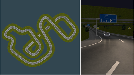
LucidDrive, a night driving simulator helps assess automotive headlamps with an emphasis on visual analysis of headlamp light distribution in various road scenarios. It provides a virtual test drive in realistic driving environments. It is an interactive tool with the ability to switch between different lamp sets, driver view positions and road types.


Creating Custom Roads & Realistic Driving Scenarios

  • Road Editor tool helps create custom test tracks and various road scenes like city or country roads, bridges, tunnels and highways, using just the polyline or spline curves.
  • Overhead sign boards, trees, poles, road markers and pedestrians can be added to create realistic driving scenarios.


Beam Pattern Analysis of Headlamps

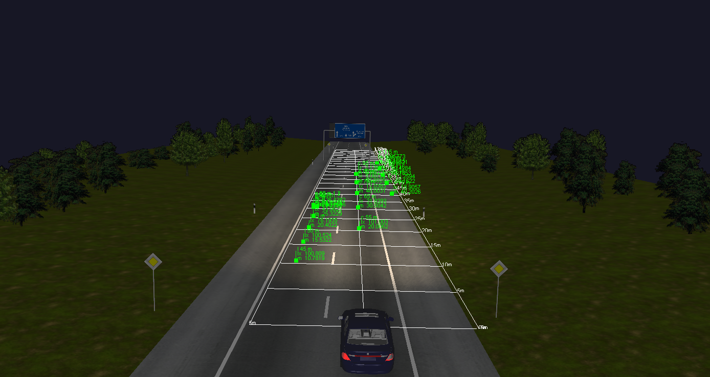
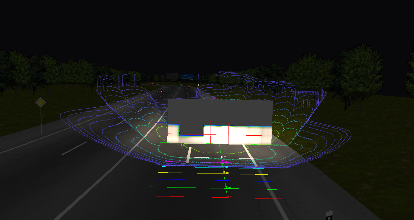
  • Mount different headlamps by defining their separation widths, height and aiming positions.
  • Switch between various sets of headlamps to see the differences in beam patterns
  • Define distance marker lines to provide target positions for visibility benchmarking.
  • Add sensors on road, sign boards and other vehicles to determine the lux values at various locations.


Simulate Pixel Light Technology with AFS Masking

LucidDrive simulates pixel light technology by detecting oncoming or overtaking traffic, and calculating bounding boxes. Defining a dimming matrix to quickly configure pixel light distributions. The sensor allows storage of dynamic light distribution and dimming matrix for each frame.


Realistic Traffic Simulations

  • Set user-defined parameters, such as vehicle speed, acceleration, deceleration and braking capabilities.
  • Simulate customized vehicle behaviour such as lane changing and overtaking.

This feature provides realistic simulations of headlight response to dynamic traffic and road conditions.


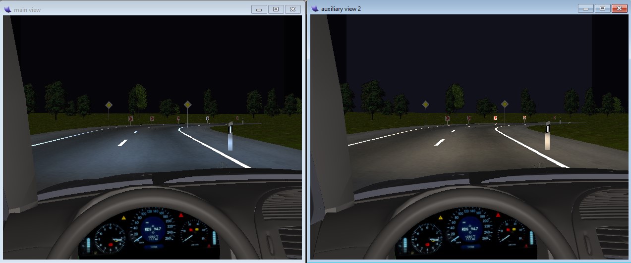
Multiple Views of Headlamp Beam Patterns

This feature helps compare multiple headlamp beam patterns simultaneously. It enables to determine the most optimal light distribution when different design configurations are being tested.  For spectrally generated intensity distribution (.LID/.IES), it is possible to view colour dispersion effects. It also offers different view positions such as the driver’s view, bird’s eye view, drone and pedestrian view which helps visualize the extent of the beam footprint over a large area.

The integration of this visual technology in new product development process will help envision the complete market ready product without the need for any physical prototypes. This improves qualitative decision making and substantially reduces development time and costs.

From Engineering to Service: Unified BOM is the Future of Product Lifecycle

In the era of digital transformation, managing a product’s lifecycle efficiently is critical. As product complexity increases and global collaboration becomes the norm, traditional siloed BOM approaches where Engineering BOM (E-BOM), Manufacturing BOM (M-BOM), and Service BOM (S-BOM) are maintained separately, lead to major challenges such as:

  • Data Inconsistencies: Different departments often work on different versions of the product structure, leading to misalignment between design, manufacturing, and service functions
  • Manual Data Duplication: Maintaining BOMs in separate systems leads to duplicate data entry and higher risk of errors
  • Inadequate Change Tracking: When E-BOM, M-BOM, and S-BOM are not synchronized, tracking and implementing changes across the product lifecycle becomes difficult, delaying product releases and increasing costs
  • Lack of Collaboration: Isolated BOM’s hinder team collaboration, leading to designs that are hard to manufacture or service due to lack of early input from downstream teams
  • Delayed Time-to-Market: Disconnected processes slow down development cycles, with BOM mismatches causing delays in manufacturing and service readiness
  • Increased Cost and Rework: Without a unified BOM, errors propagate downstream, leading to rework, scrap, warranty claims, and higher support costs.

Challenges of Siloed BOM’s

Maintaining separate BOM’s causes several operational bottlenecks like:

  • Manual Data Entry
  • Poor Change Traceability
  • Design-to-Manufacture Gaps
  • Limited Reuse
  • Data Duplication

What is Unified BOM Management?

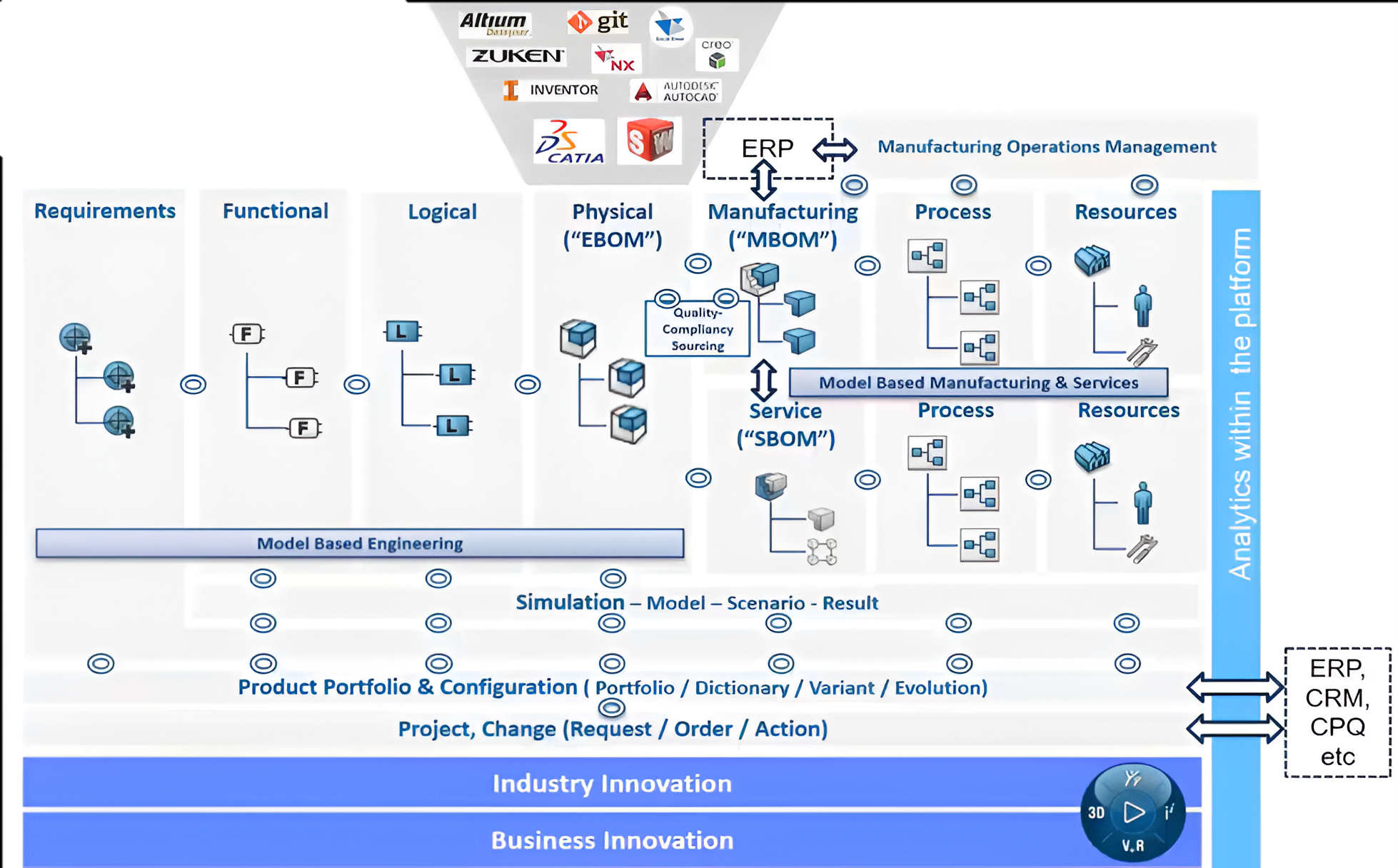
Unified BOM Management refers to maintaining a single, consistent product structure that can be extended and tailored across multiple departments – Engineering, Manufacturing, and Service. Instead of working in silos, teams can collaborate using a common data model.

Model-based Engineering is the backbone that supports real-time collaboration, traceability, and change propagation across departments.


Unified BOM Is Not Just a Trend – It’s a Necessity

To stay competitive in today’s connected, product-as-a-service world, businesses must adopt a Unified BOM strategy. It enables seamless collaboration, faster product development, and more efficient service delivery.

Organizations should think about unifying engineering, manufacturing, and service data into a cohesive digital model, ensuring end-to-end visibility and agility.


How 3DEXPERIENCE Platform fosters Unified BOM Management

The 3DEXPERIENCE Platform fosters a Unified Bill of Materials (BOM) Management by providing a centralized and collaborative environment that integrates people, processes, and data across the entire product lifecycle. It enables unified BOM management through the following key capabilities:

  • Collaborative Engineering Definition: Enables cross-functional teams to define and manage the engineering BOM in a shared digital environment.


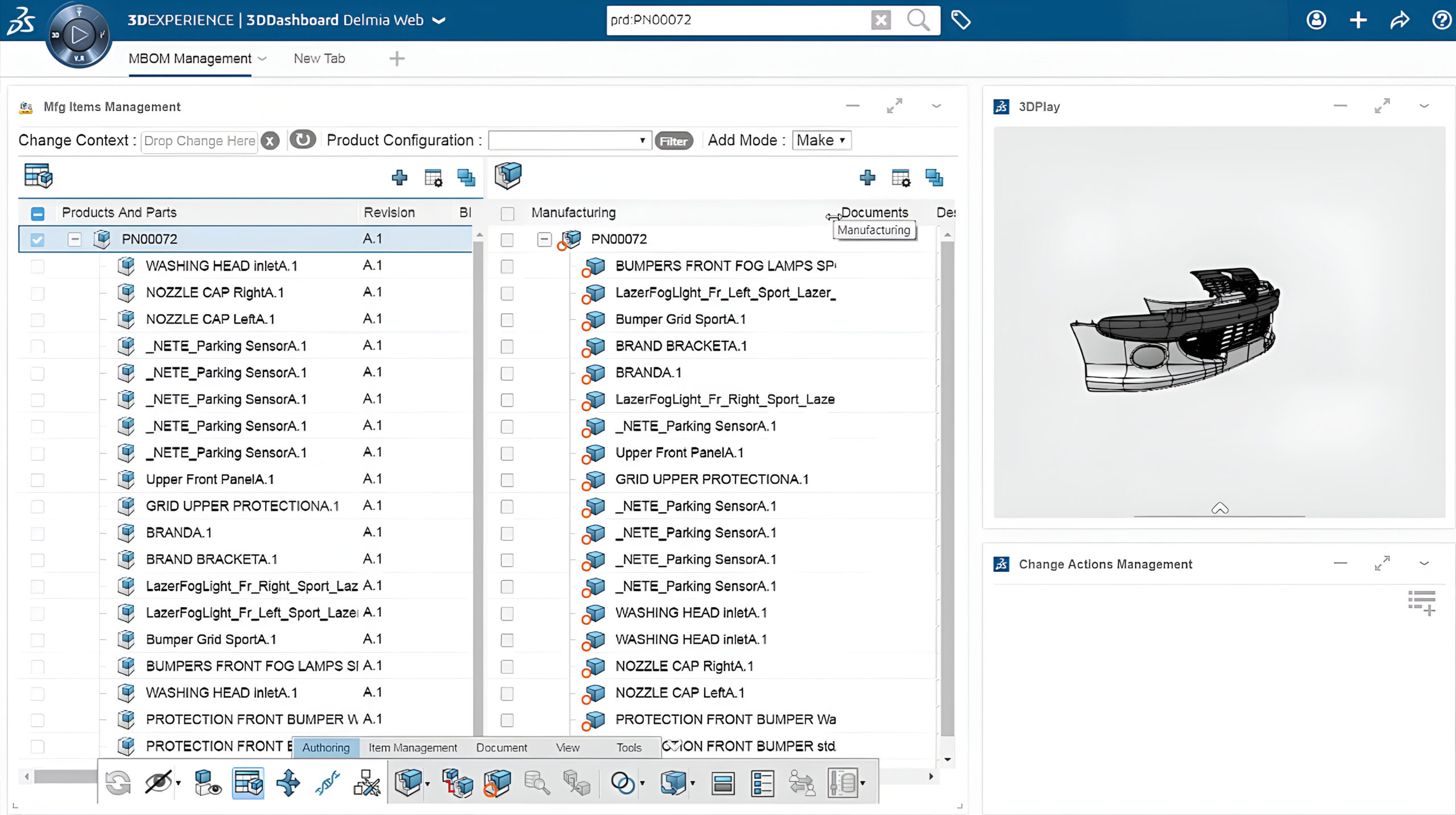
  • Collaborative Engineering to Manufacturing: Ensures seamless transformation of the engineering BOM into a manufacturing BOM, supporting alignment between design and production


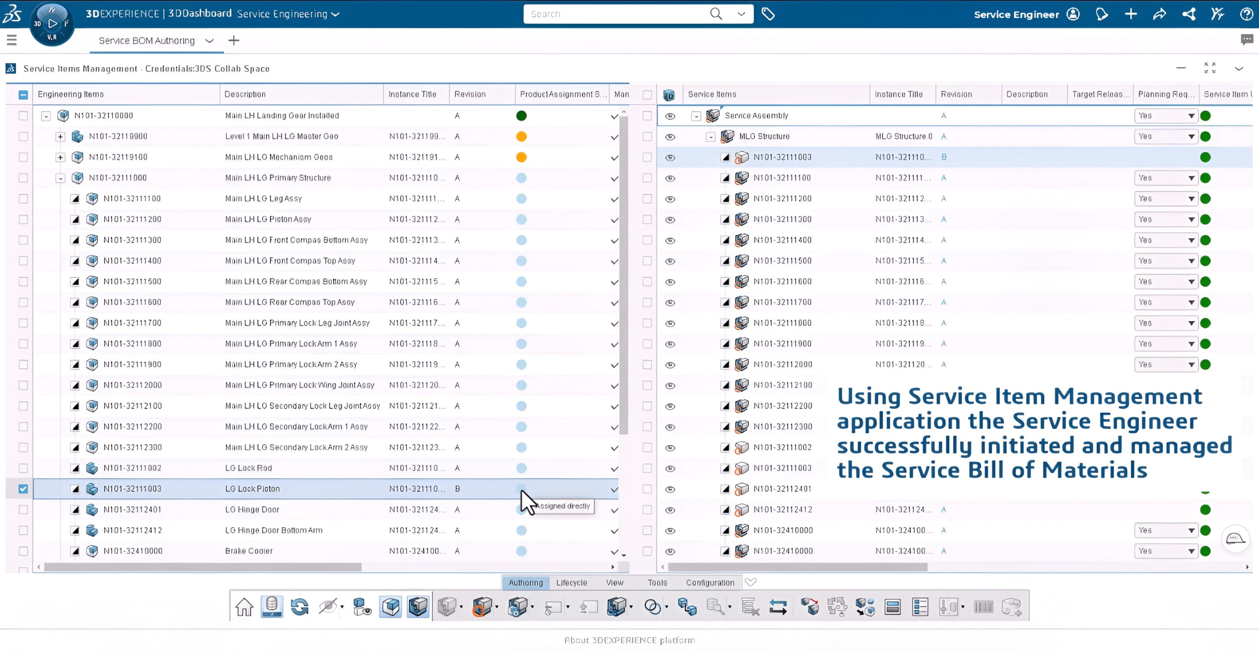
  • Service Process Engineering: Extends BOM usability into service planning by incorporating service requirements and creating service BOM’s linked to the product definition

To get more information & insights on how the 3DEXPERIENCE Platform drives Unified BOM Management, please reach out to us at marketing@edstechnologies.com 

Unlocking the Power of Pure Copper with EOS M290 1kW system

In the evolving world of Additive Manufacturing (AM), precision, performance, and material integrity are critical. One of the most transformative developments in this field is the ability to 3D print pure copper and copper alloys with high electrical and thermal conductivity — materials once considered extremely challenging due to their reflectivity and thermal behavior.

Thanks to the advancements in EOS metal 3D printing systems, particularly the EOS M 290 with 1kW laser configuration developed by AMCM (an EOS Group company), manufacturing complex, high-performance copper parts is now a reality.


Why Print with Pure Copper?

Pure copper is renowned for its exceptional conductivity, but its high reflectivity and thermal conductivity pose significant hurdles in laser-based 3D printing. EOS has overcome this with tailored process parameters and specialized hardware:

Copper and its alloys are vital for applications such as:

  • Heat exchangers
  • Electrical connectors and windings
  • Rocket engine components
  • Induction coils
  • Marine impellers

Traditionally, producing complex geometries in these materials was time-consuming, wasteful, and restrictive. With Direct Metal Laser Solidification (DMLS), EOS enables geometrical freedom, material efficiency, and functional performance — redefining how copper is used in manufacturing.


EOS Copper Portfolio at a Glance

EOS Copper Cu (Pure Copper for EOS M 290 – 400W Laser)

  • Conductivity: >90% IACS (heat-treated)
  • Mechanical Strength: 180 MPa yield, 200 MPa tensile
  • Layer Thickness: 20 µm
  • Use Case: Early adoption and R&D for heat exchangers, electronics

A solid choice for foundational pure copper applications where moderate build rates and high conductivity are essential.


EOS Copper CuCP (Commercially Pure Copper for AMCM M 290 – 1kW Laser)

  • Purity: >99.95%
  • Conductivity: Up to 102.6% IACS (heat-treated)
  • Elongation at Break: Up to 55%
  • Layer Thickness: 40 µm
  • Volume Rate: 5.4 mm³/s
  • TRL: 5
  • Use Case: Inductors, high-current connectors, electric motors

With dual exposure strategies (bulk and application-specific), CuCP balances conductivity, productivity, and repeatability — even across multiple powder reuses.


EOS CopperAlloy CuCrZr (Strength + Conductivity for AMCM M 290 – 1kW Laser)

  • Yield Strength (HT): 210 MPa
  • Tensile Strength (HT): 340 MPa
  • Conductivity (HT): >80% IACS
  • Volume Rate: 15.4 mm³/s
  • Layer Thickness: 80 µm
  • Use Case: Rocket nozzles, high-stress coils, heat sinks

An ideal choice for components requiring durability under heat and pressure — bridging structural integrity with electrical function.


EOS Copper Alloy CuNi30 (Saltwater-Resistant Alloy for EOS M 290 & M 400-1)

  • Excellent corrosion resistance in salt water
  • Yield Strength (HT): Up to 560 MPa
  • Tensile Strength (HT): Up to 700 MPa
  • Layer Thickness: 60 µm
  • Volume Rate: 5.2 mm³/s
  • Use Case: Marine parts, impellers, offshore pump housings

CuNi30 offers marine-grade protection and strength — performing reliably even in low temperatures and aggressive environments.


Built on the EOS Quality Triangle

Every material developed by EOS aligns with its Quality Triangle: System, Material, and Process. This ensures consistent, repeatable results — whether you’re building a powertrain coil, a marine pump, or a next-gen electric drive.

From TRL 3 exploratory materials to TRL 7+ validated products, EOS supports the entire adoption curve — from research to production.


Real Impact, Real Innovation

EOS metal systems make what was once impossible, now industrially viable:

  • High conductivity copper parts printed directly, with minimal post-processing
  • Optimized exposure strategies for delicate features like windings and thin walls
  • Heat treatments tailored for specific mechanical and thermal outcomes
  • Minimized defects, even after multiple powder reuses

The convergence of material science, laser power, and process know-how empowers designers and engineers to innovate without constraint.


EOS Metal Systems: Tailored for Copper Printing

EOS doesn’t just supply powders — it delivers a complete solution. Their Quality Triangle approach integrates system, material, and process, ensuring consistent output across industries. EOS M 290 configurations (standard and 1kW variants) deliver:

  • Closed-loop thermal monitoring
  • Precision recoating mechanisms
  • Software-controlled exposure profiles
  • Compatibility with argon-protected atmospheres for material purity

Final Thoughts: Applications Driving Demand

Industries such as aerospace, automotive, energy, and electronics are increasingly adopting copper AM parts for:

  • Weight-optimized heat sinks and exchangers
  • Compact, complex geometries in RF and inductive components
  • Conformal cooling and embedded circuitry in power systems

By enabling the additive manufacture of high-conductivity copper and alloy parts, EOS empowers engineers to design for function without compromise — ushering in a new era of metal AM performance.

Subscribe to our newsletter

Get all the latest information on Events, Sales and Offers.