Identify Stray Light in Imaging Systems with LightTools
- Niharika R K
- June 24, 2026
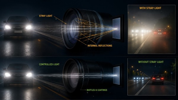
Stray light is undesired light radiation that interacts with the components of a system and degrades its performance by generating noise, that significantly reduces image quality and affects accuracy. These unintended reflections or scattering of light can be either from the object that the optical system is capturing or external emitters such as the sun or moon in case of cameras and telescopes.
Stray light could distort colours, prevent detection, affect contrast and data readability that tend to severely impact safety and efficiency. For example, the ADAS system in vehicles rely on multiple cameras for detection but the headlamps of on-coming traffic could affect the visual information being processed. Similarly, in medical imaging systems poor contrast and distortion could affect accurate diagnosis and treatment.

Fig.1. Examples of flare and ghost images in photos taken with a camera
To limit undesirable light reflections to a minimum, baffles, stop surfaces, or surface treatment/anti-reflective coatings can be used. However, the first step is to identify the source of stray light and examine the optical paths that create it.
Engineers can leverage LightTools optical design engineering software to accurately model the real-world performance of such systems and address stray light effects at the design stage itself, thus reducing multiple iterations and increasing efficiency.
LightTools Workflow For Stray Light Analysis
The aim is to examine the impact of reflections from lens surface and identify its optical path.
- Open or import the lens model into LightTools. Align the geometry according to the global axis system and ensure all lens surfaces are grouped together and named sequentially.
- Assign material properties to all components of the system, including lens, mirrors, baffles, mechanical mounts from the material library.
- Choose optical property for the lens surfaces and the ray trace method. This defines if the surfaces will be reflecting, transmitting or has probabilistic ray split with Fresnel loss
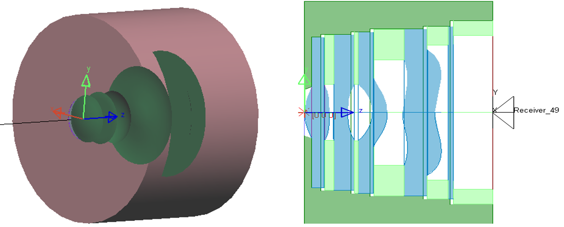
Fig.2. geometry of lens system in LightTools and its wireframe section view
- Multiple configurations with varying optical /material properties or any independent input variable can be created at once. This helps to evaluate more than one design concept simultaneously without needing to create the model from scratch.
- Define an object source, this could simply be a rectangular plane source the size of the image or the actual image itself can be used as a source with the image processor utility.
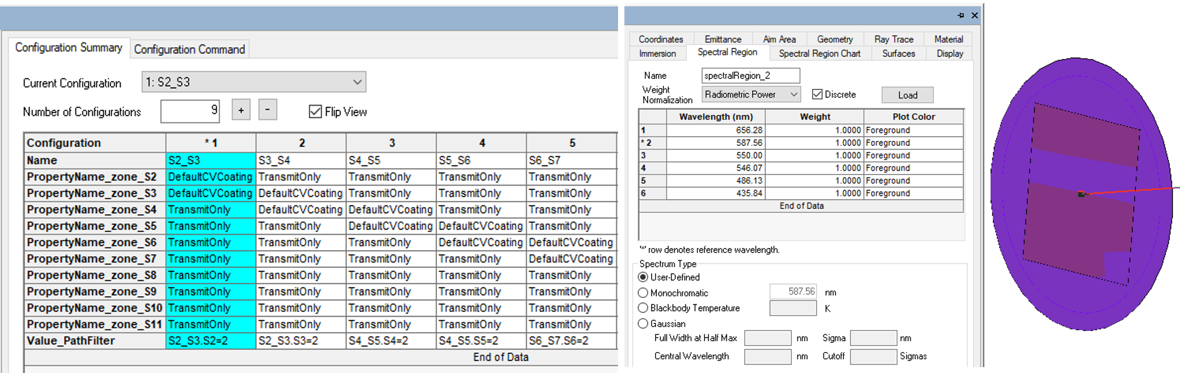
Fig.3. define multiple configurations simultaneously(left) and a plane light source creation (right)
- Multiple configurations with varying optical /material properties or any independent input variable can be created at once. This helps to evaluate more than one design concept simultaneously without needing to create the model from scratch.
- Define an object source, this could simply be a rectangular plane source the size of the image or the actual image itself can be used as a source with the image processor utility.
- Add receiver filter to the exit surface and input the ray trace parameters to run the simulation. Check the ray path collection is enabled for the receiver as this will record the complete data for each optical path traced through the system. Run the Monte-Carlo ray trace.
- Analyse the Illuminance patterns for each configuration interactively or using the parameter analyser. The ray paths traversed through the system and its corresponding illumination pattern could be visualized individually using the Ray Path tool.
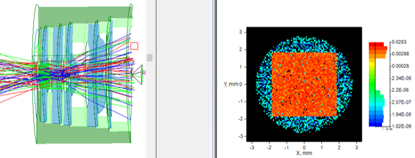
Fig.4. Visualizing rays traced through the system using Ray Path tool and its corresponding illuminance pattern
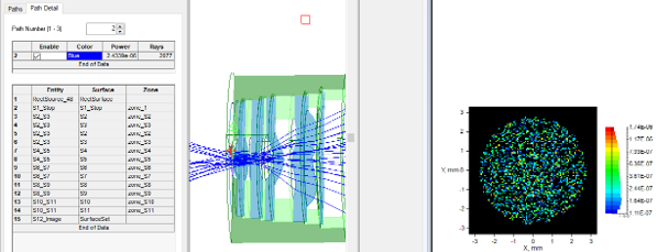
Fig.5. Ray path causing double reflections, path details and the corresponding stray light illuminance pattern produced
The tool provides complete data about the sequence of surfaces the rays are traced through and the total power, along with the illuminance pattern.
It assists engineers in detecting direct and single-bounce reflections from optical and mechanical surfaces, as well as where the ghost images will land, their size, and brightness, dependent on the geometry and coatings of each optical surface. Identifying the worst reflection pairs will help tweak the surface to reduce impact on final image.
By integrating Keysight LightTools into your early-stage workflow, you can proactively eliminate critical stray light and ghosting issues before they reach production

Recent Posts
-
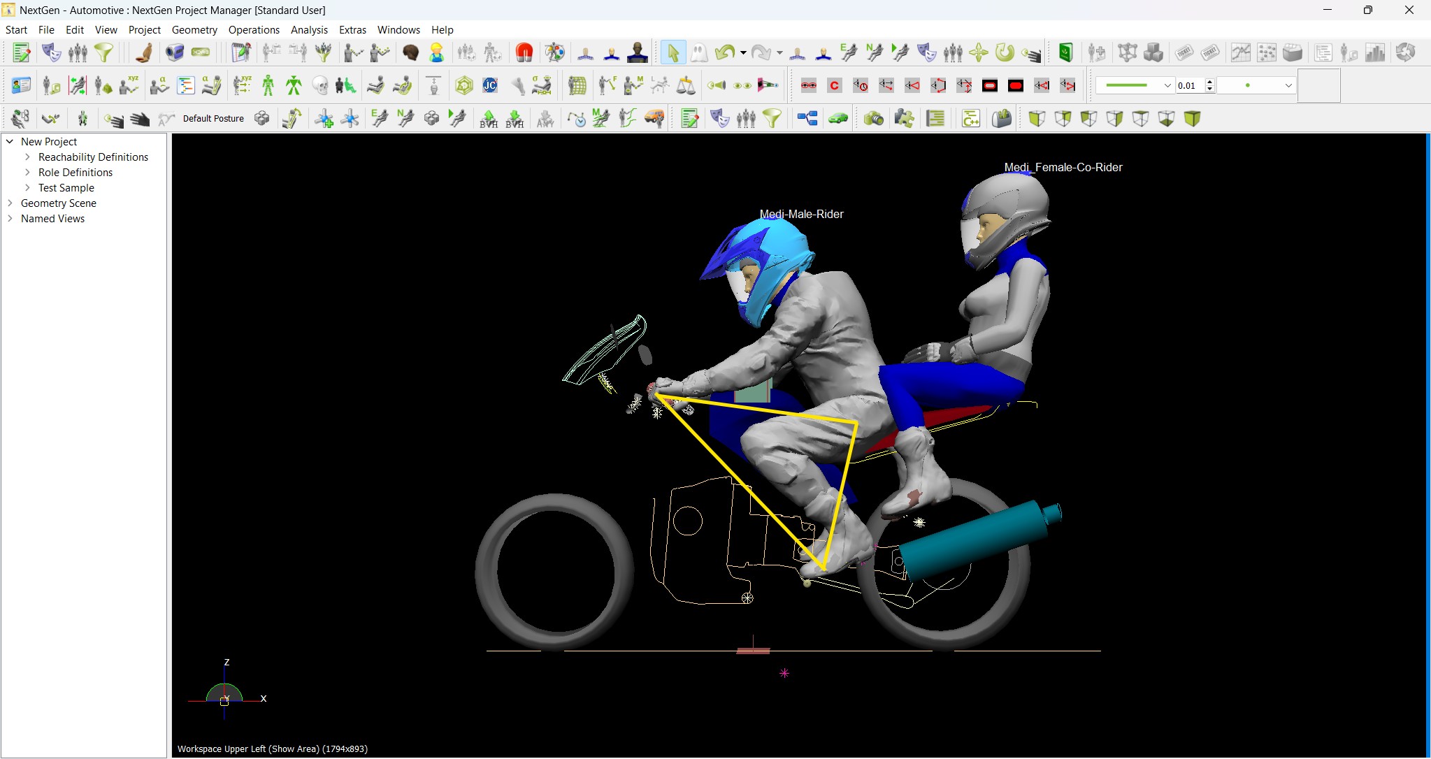
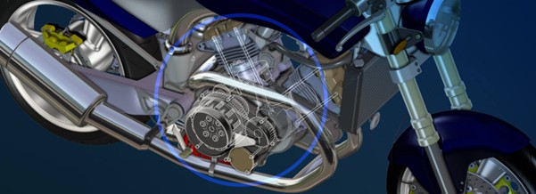
Redefining the Riding Experience with RAMSIS
In two‑wheeler design, comfort and safety start with the rider. RAMSIS (Realistic Anthropometric Mathematical System of Interior Comfort Simulation) is an ergonomic simulation platform that…
-

Enhancing Product Understanding through 3D Technical Illustrator
The 3D Technical Illustrator role within the 3DEXPERIENCE Platform enables organizations to transform complex engineering data into clear, interactive, and visually rich technical documentation. In…
-
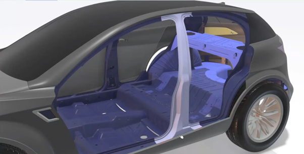
Transforming Physical Parts into Digital Models with CATIA 3DEXPERIENCE Reverse Engineer role
Reverse engineering has become a critical capability in modern product development, especially when working with legacy components, competitor benchmarking, or physical prototypes that lack digital…
-
Fixing Search Service Down Issue in 3DEXPERIENCE Platform
Search is one of the most critical features in the 3DEXPERIENCE platform. If the search service goes down, users cannot find objects, documents, or data—impacting…
-
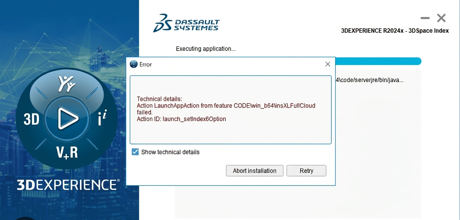
Common Installation Errors and How to Fix Them in 3DEXPERIENCE
The 3DEXPERIENCE Platform is a powerful solution used by industries worldwide for product lifecycle management (PLM), simulation, and collaboration. However, installing 3DEXPERIENCE—especially on-premise—can be complex…
-

From Classroom to Industry: Empowering Future Engineers with the 3DEXPERIENCE Platform
In today’s fast-evolving engineering and design landscape, educational institutions must go beyond conventional CAD teaching methods. While standalone tools like CATIA V5, SOLIDWORKS, or traditional…
-
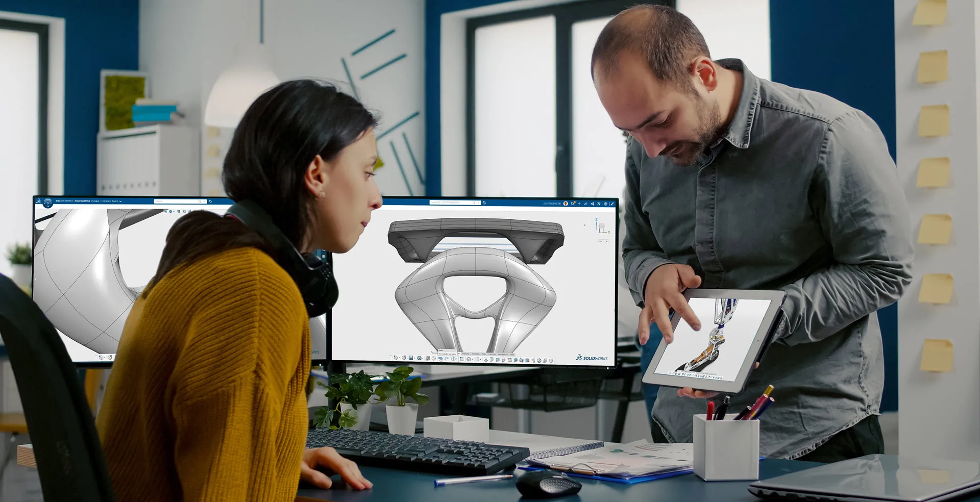
CATIA Composer – Transforming Engineering Data into Interactive Technical Documentation
CATIA Composer is a powerful desktop application from Dassault Systemes designed to transform engineering 3D CAD data into highly intuitive and interactive technical documentation. In…
-
3DEXPERIENCE CATIA Composite Design – Delivering Next-Generation Precision for Advanced Composite Structures
3DEXPERIENCE CATIA Composite Design is an advanced, collaborative, and highly integrated engineering solution designed to manage the complexity of modern composite structures used across aerospace,…
- Niharika R K
- June 24, 2026
Identify Stray Light in Imaging Systems with LightTools
Stray light is undesired light radiation that interacts with the components of a system and degrades its performance by generating noise, that significantly reduces image quality and affects accuracy. These unintended reflections or scattering of light can be either from the object that the optical system is capturing or external emitters such as the sun or moon in case of cameras and telescopes.
Stray light could distort colours, prevent detection, affect contrast and data readability that tend to severely impact safety and efficiency. For example, the ADAS system in vehicles rely on multiple cameras for detection but the headlamps of on-coming traffic could affect the visual information being processed. Similarly, in medical imaging systems poor contrast and distortion could affect accurate diagnosis and treatment.
Fig.1. Examples of flare and ghost images in photos taken with a camera
To limit undesirable light reflections to a minimum, baffles, stop surfaces, or surface treatment/anti-reflective coatings can be used. However, the first step is to identify the source of stray light and examine the optical paths that create it.
Engineers can leverage LightTools optical design engineering software to accurately model the real-world performance of such systems and address stray light effects at the design stage itself, thus reducing multiple iterations and increasing efficiency.
LightTools Workflow For Stray Light Analysis
The aim is to examine the impact of reflections from lens surface and identify its optical path.
- Open or import the lens model into LightTools. Align the geometry according to the global axis system and ensure all lens surfaces are grouped together and named sequentially.
- Assign material properties to all components of the system, including lens, mirrors, baffles, mechanical mounts from the material library.
- Choose optical property for the lens surfaces and the ray trace method. This defines if the surfaces will be reflecting, transmitting or has probabilistic ray split with Fresnel loss
Fig.2. geometry of lens system in LightTools and its wireframe section view
- Multiple configurations with varying optical /material properties or any independent input variable can be created at once. This helps to evaluate more than one design concept simultaneously without needing to create the model from scratch.
- Define an object source, this could simply be a rectangular plane source the size of the image or the actual image itself can be used as a source with the image processor utility.
Fig.3. define multiple configurations simultaneously(left) and a plane light source creation (right)
- Multiple configurations with varying optical /material properties or any independent input variable can be created at once. This helps to evaluate more than one design concept simultaneously without needing to create the model from scratch.
- Define an object source, this could simply be a rectangular plane source the size of the image or the actual image itself can be used as a source with the image processor utility.
- Add receiver filter to the exit surface and input the ray trace parameters to run the simulation. Check the ray path collection is enabled for the receiver as this will record the complete data for each optical path traced through the system. Run the Monte-Carlo ray trace.
- Analyse the Illuminance patterns for each configuration interactively or using the parameter analyser. The ray paths traversed through the system and its corresponding illumination pattern could be visualized individually using the Ray Path tool.
Fig.4. Visualizing rays traced through the system using Ray Path tool and its corresponding illuminance pattern
Fig.5. Ray path causing double reflections, path details and the corresponding stray light illuminance pattern produced
The tool provides complete data about the sequence of surfaces the rays are traced through and the total power, along with the illuminance pattern.
It assists engineers in detecting direct and single-bounce reflections from optical and mechanical surfaces, as well as where the ghost images will land, their size, and brightness, dependent on the geometry and coatings of each optical surface. Identifying the worst reflection pairs will help tweak the surface to reduce impact on final image.
By integrating Keysight LightTools into your early-stage workflow, you can proactively eliminate critical stray light and ghosting issues before they reach production