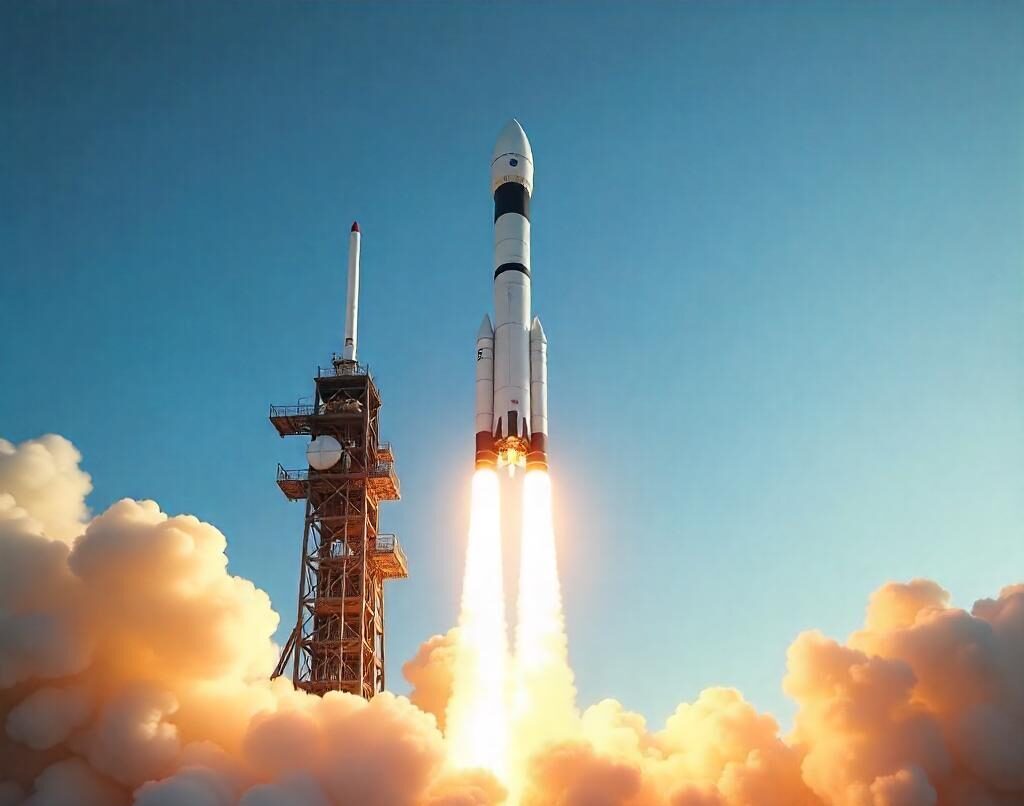
The space industry is at the forefront of technological advancement, with its unique challenges demanding cutting-edge tools for design and engineering. From satellites and spacecraft to rockets and space stations, the need for precision, collaboration, and innovation is unparalleled. This is where 3DEXPERIENCE CATIA shines, empowering organizations to transform their ideas into reality while overcoming the complexities of space exploration.
Addressing the Unique Challenges of Space Design
- Extreme Precision: Components must withstand the harsh conditions of space, including extreme temperatures, vacuum environments, and radiation.
- Weight Optimization: Every gram counts, as launch costs are heavily influenced by payload weight.
- Complex Systems Integration: Spacecraft involve intricate systems that need seamless integration, from propulsion and avionics to communication and life support.
- Global Collaboration: Teams across the globe often contribute to a single mission, necessitating streamlined communication and data sharing.
Advanced Capabilities for Space Design
- Parametric and Generative Design: CATIA’s parametric modelling enables engineers to create highly detailed and adaptable designs. Generative design capabilities further allow teams to explore innovative structures optimized for weight and strength, which is essential for space applications.
- Multiphysics Simulation: Space components must endure extreme stresses. CATIA’s integration with simulation tools allows for detailed analysis of thermal, structural, and aerodynamic properties, ensuring reliability under harsh conditions.
- Virtual Twin Technology: The Virtual Twin Experience on the 3DEXPERIENCE platform allows designers to create a digital replica of a spacecraft, enabling real-time analysis, testing, and optimization before physical prototypes are built.
Enhancing Collaboration in Space Projects
The 3DEXPERIENCE platform facilitates seamless collaboration across teams and disciplines. With a centralized data repository, stakeholders can access the latest design iterations, provide feedback, and ensure alignment throughout the development process.
- Real-Time Collaboration: Engineers, scientists, and project managers can work on the same model simultaneously, regardless of location.
- Traceability and Compliance: The platform ensures that every design decision is documented, aiding in compliance with aerospace regulations.
- Stakeholder Engagement: Visual and immersive tools help non-technical stakeholders understand and contribute to design decisions.
Success Stories in Space Design
Organizations leveraging 3DEXPERIENCE CATIA have achieved remarkable milestones in space exploration. From designing lightweight satellite structures to developing reusable rocket components, CATIA has proven its versatility and reliability in driving innovation.
Sustainability in Space Design
Sustainability is becoming a critical concern in the space industry. With CATIA, teams can:
- Optimize designs to minimize material waste.
- Explore the use of eco-friendly materials.
- Improve energy efficiency in manufacturing and operations.
Conclusion
The space industry’s demands for innovation, precision, and collaboration are met with unparalleled effectiveness by 3DEXPERIENCE CATIA. By enabling teams to design, simulate, and optimize within a unified platform, CATIA is not just a tool but a catalyst for the next frontier of exploration. As we continue to push the boundaries of what is possible, CATIA will remain an indispensable partner in crafting the future of space exploration.

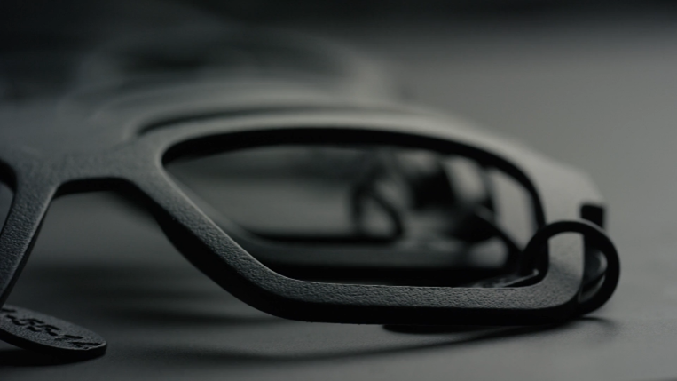
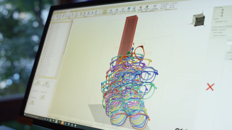
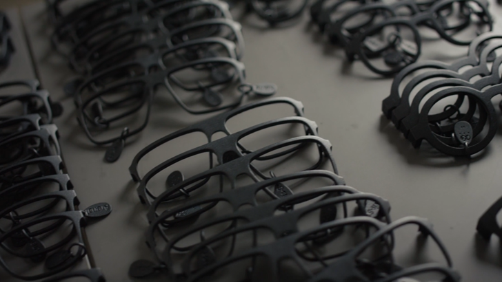
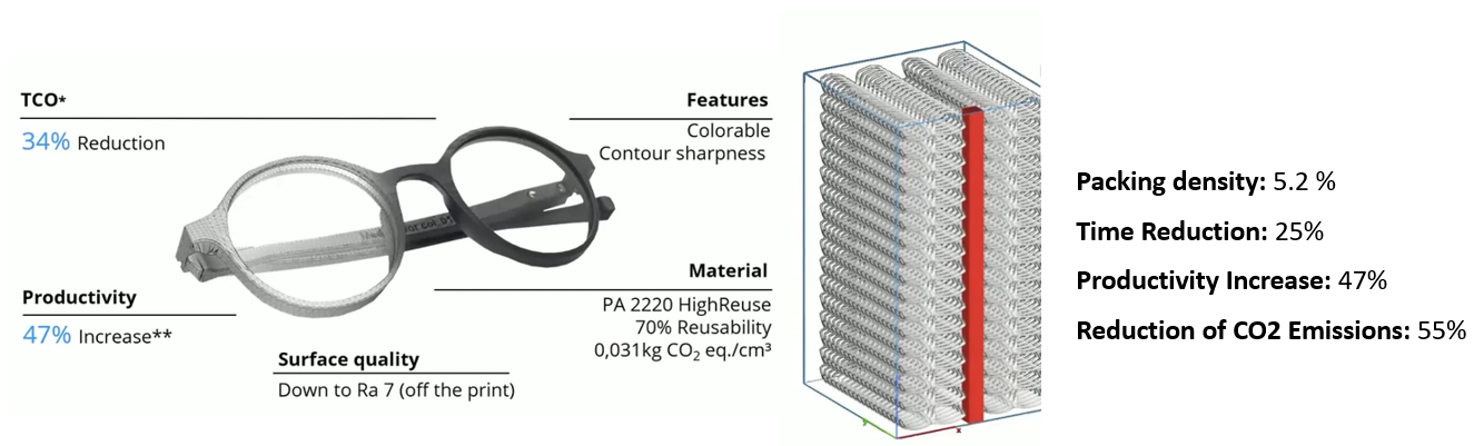
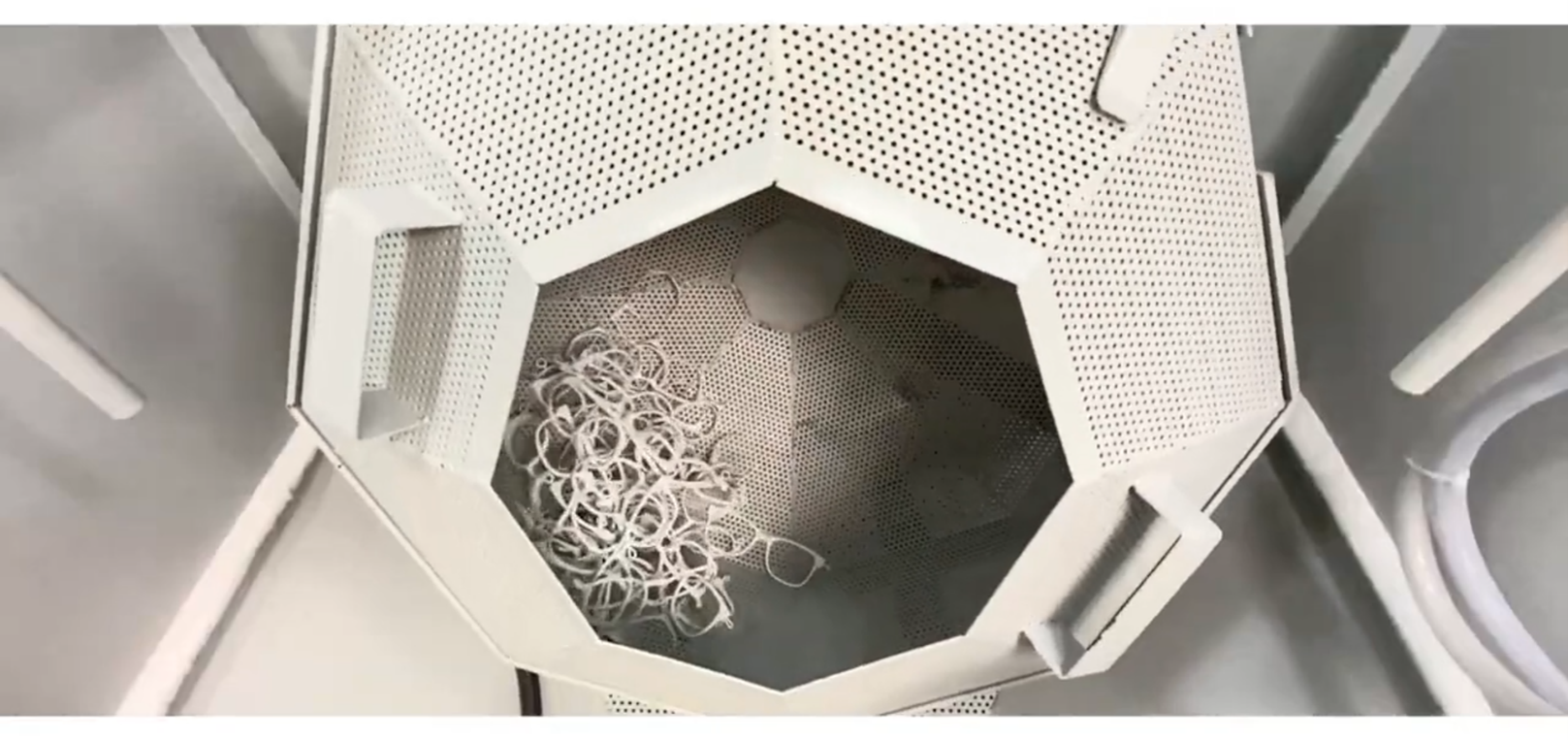 Fig. 3: Scaled Finishing process for Production of Eyewear