Troubleshooting Abaqus/Explicit analyses that use contact pairs

- Vignesh Pagadalu
- October 22, 2020
This blog explains the different errors encountered while using Abaqus/Explicit and the ways to debug and troubleshoot them.
Tracking Difficulties
- Reason: By default, Abaqus/Explicit uses a fast, local tracking algorithm to track the penetration of a slave node into the master surface; at a frequency of every 100 increments (the user can change this default), Abaqus/Explicit performs a global search. If penetration by a slave node goes undetected for a period of time (in between the global searches), the code may allow the penetration to go unresolved and a large correction (or force) may be required to overcome the penetration when it is finally detected. A high velocity is imparted to the nodes that had penetrated the contact surfaces but were not detected as over-penetrated; this high rate of deformation causes problems such as severe element distortion.
- Debugging: Create a history plot of global energy quantities ALLIE and ALLKE for every time increment prior to termination. If a contact correction is the reason for termination, there will be a large spike in ALLKE just prior to the termination point.
In addition, create vector plots of A and CFORCE from the state just prior to termination. Look for evidence of contact force values and accelerations (and the corresponding locations) that are much higher than elsewhere in the model, particularly on contact surfaces and in the region of the node or element number indicated in the error message.
If necessary, rerun or restart the analysis to get this information. If the penetration goes undetected during the analysis, no diagnostic messages will be printed. However, this problem can be seen by looking at the deformed shape of the model and checking that the contact pressures and opening make sense.
- Caution: In the event of a restart analysis, the problem might not reproduce itself due to step initialization and the fact that the initial time increment will not replicate the one used in the original analysis (at the start of every step, an element-by-element time estimator is used; later, a global time estimator is used). If you are running a multi-step analysis and several steps complete prior to termination, it is better to restart from the beginning of the last completed step.
- Remedy: Increase the frequency of the global contact tracking
-
- Abaqus/CAE: Interaction Module: Interaction → Contact Controls → Create… → Global Search Frequency
- Keyword: *CONTACT CONTROLS, CPSET=contact_pair_set_name, GLOBALTRKINC=n and/or use the more conservative local tracking algorithm
- Abaqus/CAE: Interaction Module: Interaction → Contact Controls → Create… → unselect Fast local tracking
- Keyword: *CONTACT CONTROLS, CPSET=contact_pair_set_name, FASTLOCALTRK=NO
-
Hourglassing
- Reason: Abaqus/Explicit generally offers first-order reduced-integration elements, which may be susceptible to hourglassing. When mesh refinement is inadequate, hourglassing may cause nonphysical deformation modes that, when coupled with contact constraints, can lead to severe contact penetrations. This is particularly true when contact occurs at a single node.
- Debugging: Plot the global energy histories ALLIE and ALLAE for all increments up to termination. If ALLAE is a significant fraction of ALLIE, hourglassing has occurred. In addition, inspect the deformation pattern of the mesh at times prior to failure. If a regular pattern of element distortion is clearly visible in the deformed mesh (you may have to increase the magnification factor to see it), hourglassing is probably occurring.
- Remedy: The enhanced hourglass control method, which is based on the enhanced assumed strain method, may help. Use:
-
- Abaqus/CAE: Mesh module: Mesh → Element Type… → Hourglass control: Enhanced
- Keyword: *SECTION CONTROLS, NAME=name, HOURGLASS=ENHANCED
-
If you have decided not to use the enhanced hourglass control approach, refine the mesh and try to distribute the contact over several nodes (for example, change sharp corners to round corners). Increasing the hourglass stiffness is usually not the best solution. If mesh refinement does not cure the hourglassing, try using a different type of hourglass control.
If you need to increase the hourglass stiffness, use:
- Abaqus/CAE: Mesh module: Mesh → Element Type… → Hourglass control: type_of_hourglass_control
- Keyword: *SECTION CONTROLS, NAME=name, HOURGLASS=type_of_hourglass_control where type_of_hourglass_controlis:
-
- RELAX STIFFNESS for the default integral viscoelastic approach
- STIFFNESS for the Kelvin viscoelastic stiffness approach
- VISCOUS for the Kelvin viscoelastic viscous approach
- COMBINED, WEIGHT FACTOR= for the stiffness and viscous Kelvin viscoelastic approach
-
Material instability
- Reason: Material instability may occur near a contact interface because contact may be the first type of loading on a structure. Since contact is frequently a sudden load (such as in an impact), the loading may be severe enough to cause the material to go unstable.
- Debugging: Usually this problem is characterized by a large acceleration without a corresponding large reaction force at a contact node (the acceleration is due to the element’s internal force rather than an external force).
- Remedy: Check the material definition to ensure stability requirements are satisfied (in particular for hyper elastic materials). If the material stability requirements are met, try applying the contact gradually to reduce its severity. Use velocity boundary conditions, or use the smooth-step amplitude definition.
Initial overclosures
- Reason: Abaqus/Explicit does not permit any initial overclosures. The nodes on the contacting surfaces are adjusted to remove the initial overclosure. Corrections at the beginning of an analysis do not induce strains; later adjustments cause strains. Thus, if the initial overclosure is too large in steps other than the first, the corresponding contact correction may be too large and cause significant deformation in the elements.
With balanced master-slave contact or when nodes are slaves to more than one master surface (i.e., pinched contact), it is possible to have unresolved initial overclosures. These will result in large initial accelerations, which can lead to significant mesh distortion. The unresolved overclosures are reported to the status (.sta) file.
Adjacent slave nodes (i.e., those connected by a facet) that initially lie on either side of a double-sided surface will be corrected so that each slave node is moved to the nearest free surface (thus, the slave nodes will be moved to opposite sides of the master surface).
Warnings for such a case are issued when the slave nodes are defined as part of a surface but not when they are defined through node-based surfaces (i.e., contact node sets). This will lead to contact difficulties if not corrected.
- Debugging: Check your model for evidence of initial overclosures. In particular, remember to consider the thickness of a shell when positioning bodies relative to one another. If introducing a new contact pair in a later step (for example, adding a new rigid punch and die), take into account any deformations that may have occurred up to that point when positioning the new features.
In addition, check for incorrect surface normals. For single-sided contact the surface normal must be consistent and point toward the opposing surface.
To understand what is happening, try to simplify the model to include only the region near the large accelerations. Adjusting the weighting of the contact pair (or pairs) often helps.
- Remedy: Reposition surfaces to remove the initial overclosures. Reverse surface normal definitions if necessary. If surfaces are being pinched, make the pinched surfaces master surfaces if possible.
Overconstraining the model with MPCs and equations
- Reason: Overconstraining nodes with MPCs or equations and contact conditions can generate conflicting constraints when using kinematic contact. In some cases this can lead to large distortions and contact corrections.
- Debugging: Remove the constraints one at a time to isolate the culprit.
- Remedy: Redefine or remove the constraints. Switching to penalty contact will tend to alleviate the problem as well.
Highly warped surfaces
- Reason: It is difficult to calculate the correct contact conditions when surfaces are, or become, highly warped. Warping is monitored throughout the analysis at regular intervals, and warnings are issued when warping exceeds a threshold value (the default is 20 degrees). If this happens, Abaqus/Explicit switches to a more accurate algorithm to determine the nearest point on the master surface for a slave node.
- Debugging: Significant warping is sometimes an indication of problems in the solution, so Abaqus/Explicit issues a warning message in the status (.sta) file when a threshold value of warping is exceeded (the default is 20 degrees between surface normals of adjacent elements). This message is more of an indicator of solution problems if the underlying elements of the surface are solid elements — in this case, warping is frequently a sign of hourglassing. This is a less common cause for shells and membranes. Frequently, the problems caused by highly warped surfaces in contact will trigger the “excessive wave speed” error.
- Remedy: Refine the underlying surface mesh if possible, and make sure that the surface is modelled as smoothly as possible.
Inadequate surface definitions
- Reason: Penetrations may occur because a surface is improperly or inadequately defined. For example, if large deformations are expected, the underlying surface must extend far enough to prevent a slave node from sliding around the end of the master surface. If this happens (the slave node gets behind the master surface), the slave node will be forced immediately to the master surface (to satisfy the contact constraint). This will impart very large forces and velocities to the slave node, probably causing severe element distortion.
If two-sided contact is possible (in a shell model), the contact surface must be defined properly as a double-sided contact surface.
If the contact is pure master-slave, the master surface nodes can penetrate the slave surface.
- Debugging: Check the surface definitions:
-
-
- Do they need to be extended so that slave nodes do not slide behind master surfaces?
- Is two-sided contact possible?
- Does the contact pair weighting need to be adjusted?
- Are the masses of the master and slave surfaces very different?
- Is the edge of a surface a symmetry boundary condition?
-
- Remedy: Make sure that the surfaces extend far enough so that nodal penetrations are prevented. When modelling contacts with shell elements, use two-sided contact.
If the edge of a surface is a symmetry boundary, remember to put the symmetry boundary condition on both the slave and master surfaces.
Self-contact with thick shells
- Reason: The shell thickness is considered in contact calculations. Extremely large thicknesses (greater than the spacing between nodes) will cause nodes to appear to be penetrating nearby facets even in a flat self-contact surface (a node “penetrates” the outer boundary of its neighbour even when it is impossible for it to do so physically).
- Debugging: Compare the shell thickness against a typical element dimension (edge or diagonal length).
- Remedy: Use the SCALE THICK and/or MAXRATIO parameters on the *SURFACE option to scale down the thickness used in the contact calculations on the elements forming a surface. Make sure the contact thickness is still significant relative to the facet size.
Contact with thick shells
- Reason: There is a chance of encountering tracking problems at corners (for example, only facets on one side of a corner might be considered during local tracking, but when the global tracking is done, a slave node might be detected as being over-penetrated by facets on the other edge of the corner).
The slave node in the current position will be forced back onto the contact surface, resulting in large contact forces and velocities.
- Debugging: Compare the shell thickness against a typical element dimension (edge or diagonal length).
- Remedy: Either use the NO THICK parameter on the *SURFACE option to completely ignore the element thickness when performing contact calculations. More frequent global tracking of the contact may also help.
Poor surface definition with shell offsets
- Reason: At acute corners shell offsets may result in a poorly defined contact surface (tangled midsurface). Since tracking is based on the shell midsurface, you can encounter tracking problems with a tangled surface.
- Debugging: Compare the shell thickness against a typical element dimension (edge or diagonal length).
- Remedy: Use the NO OFFSET parameter on the *SURFACE option to ignore the shell section offset when performing contact calculations.
Excessive loading rates/excessive mass scaling
- Reason: By default, loads are applied instantaneously. This type of loading imparts large kinetic energy to nodes, possibly causing excessive element distortion and/or wave speeds.
Large mass scaling can result in similar problems since the kinetic energy and material inertia of a node are scaled artificially as a result.
- Debugging: See the previous discussions on material instability and hourglassing. Check the loading rates. Are the units consistent? Check amplitude definitions (if used).
- Remedy: Reduce the loading rate or reduce mass scaling.
Multiple contact constraints on a node
- Reason: Typically this occurs when a surface is pinched between two bodies. If a slave surface is pinched between two master surfaces (or balanced master-slave contact is used), some penetration will persist in one of the contact pairs. Abaqus/Explicit cannot resolve initial overclosures for this scenario.
- Debugging: Check for large accelerations and reaction forces on the contact surfaces.
- Remedy: Use strict master-slave contact with the master surface being pinched between two slaves. Making at least one of the contact pairs use penalty contact often alleviates the solution noise when the slave surfaces are on the pinched body.
Large mass mismatch: deformable-deformable contact
- Reason: Undesirable numerical behaviour can occur for deformable-deformable contact if the nodal masses of the master nodes are orders of magnitude less than those of the slave nodes or for rigid-deformable contact if the rigid body mass is orders of magnitude less than the deformable body mass.
- Debugging: Look for tensile contact forces at the outer slave nodes of the contact region. Plots of A for nodes on the surfaces may show excessively noisy behaviour.
- Remedy: Use strict master-slave contact with the master surface containing the more massive nodes for deformable-deformable contact, or increase the mass of the rigid body reference node for rigid-deformable contact. A warning message will be printed to the message (.msg) file indicating this may be a problem. Switching to penalty contact can also alleviate the problem.
High-speed impact and resulting element distortions
- Reason: High-speed impact can cause extreme element distortion in the contact region due to the large momentum transfer in the impact region.
- Debugging: Check that other causes of contact problems have been eliminated. Consider the physics to decide if the material may actually be failing and should not be in the model once it fails.
- Remedy: If the material is actually failing, use a material failure model to remove elements before they become too distorted and cause element errors.
Recent Posts
-

Identify Stray Light in Imaging Systems with LightTools
Stray light is undesired light radiation that interacts with the components of a system and degrades its performance by generating noise, that significantly reduces image…
-
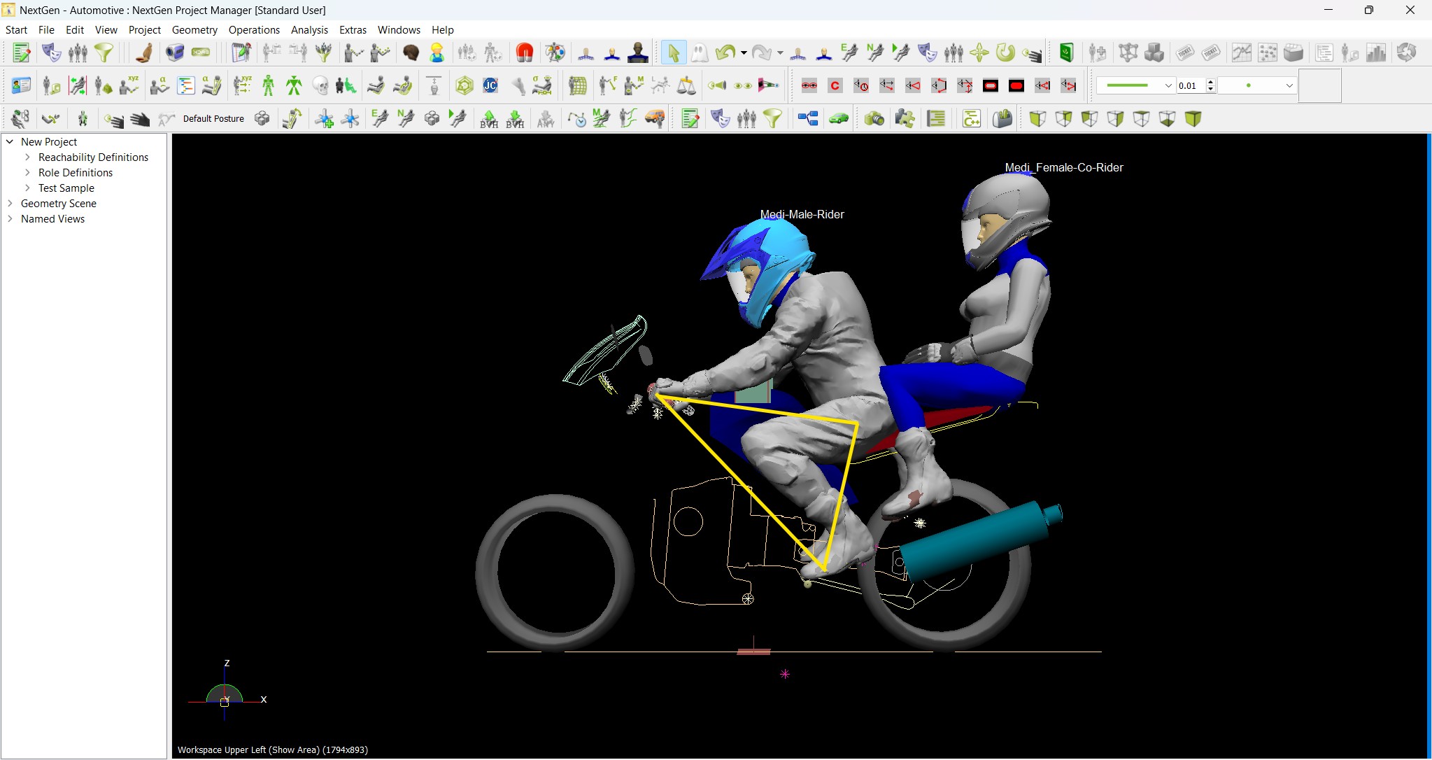
Redefining the Riding Experience with RAMSIS
In two‑wheeler design, comfort and safety start with the rider. RAMSIS (Realistic Anthropometric Mathematical System of Interior Comfort Simulation) is an ergonomic simulation platform that…
-

Enhancing Product Understanding through 3D Technical Illustrator
The 3D Technical Illustrator role within the 3DEXPERIENCE Platform enables organizations to transform complex engineering data into clear, interactive, and visually rich technical documentation. In…
-

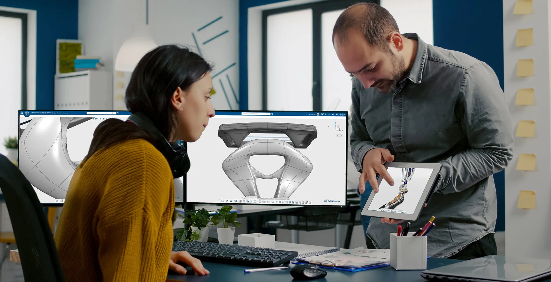
Transforming Physical Parts into Digital Models with CATIA 3DEXPERIENCE Reverse Engineer role
Reverse engineering has become a critical capability in modern product development, especially when working with legacy components, competitor benchmarking, or physical prototypes that lack digital…
-
Fixing Search Service Down Issue in 3DEXPERIENCE Platform
Search is one of the most critical features in the 3DEXPERIENCE platform. If the search service goes down, users cannot find objects, documents, or data—impacting…
-
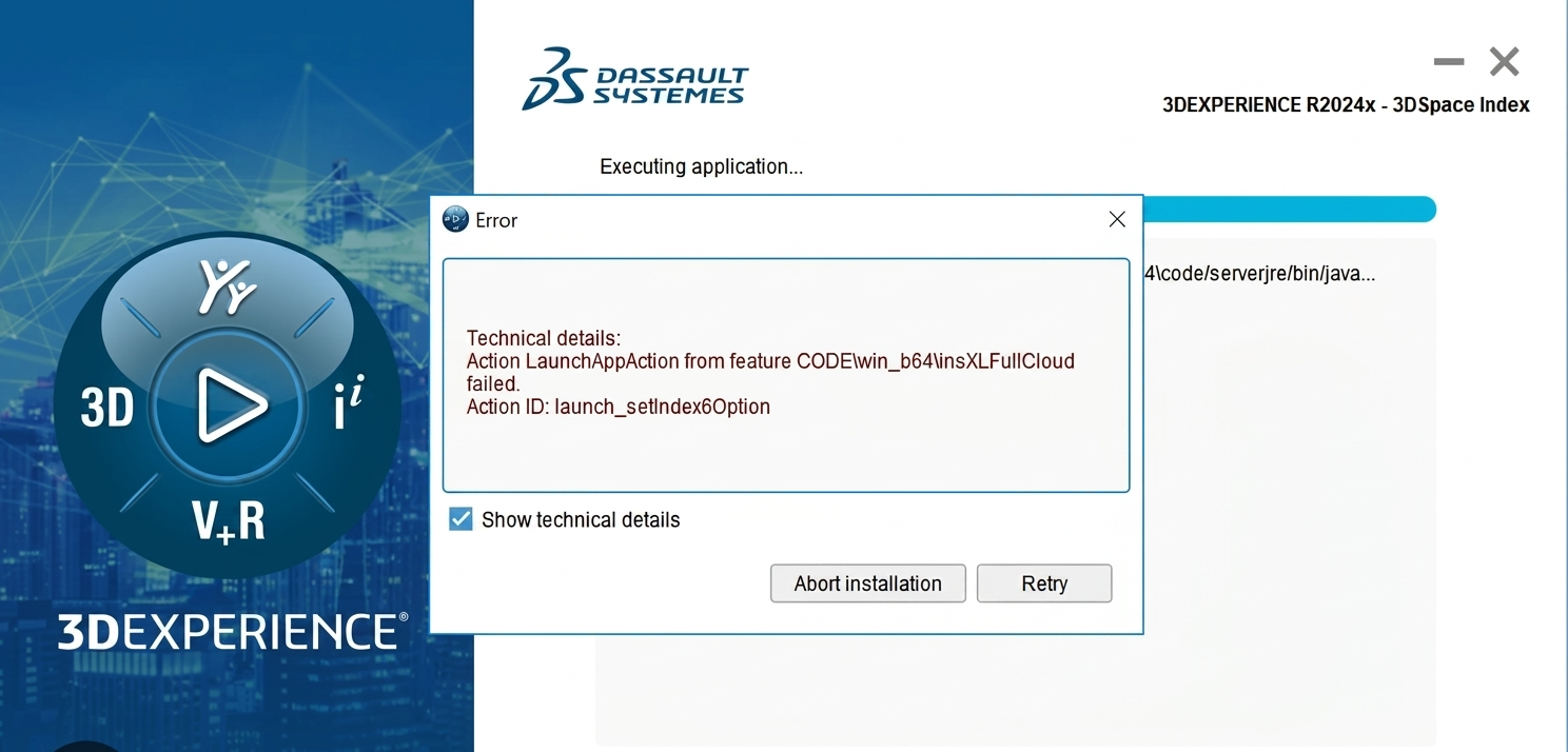
Common Installation Errors and How to Fix Them in 3DEXPERIENCE
The 3DEXPERIENCE Platform is a powerful solution used by industries worldwide for product lifecycle management (PLM), simulation, and collaboration. However, installing 3DEXPERIENCE—especially on-premise—can be complex…
-

From Classroom to Industry: Empowering Future Engineers with the 3DEXPERIENCE Platform
In today’s fast-evolving engineering and design landscape, educational institutions must go beyond conventional CAD teaching methods. While standalone tools like CATIA V5, SOLIDWORKS, or traditional…
-
CATIA Composer – Transforming Engineering Data into Interactive Technical Documentation
CATIA Composer is a powerful desktop application from Dassault Systemes designed to transform engineering 3D CAD data into highly intuitive and interactive technical documentation. In…
- Vignesh Pagadalu
- October 22, 2020
Troubleshooting Abaqus/Explicit analyses that use contact pairs
This blog explains the different errors encountered while using Abaqus/Explicit and the ways to debug and troubleshoot them.
Tracking Difficulties
- Reason: By default, Abaqus/Explicit uses a fast, local tracking algorithm to track the penetration of a slave node into the master surface; at a frequency of every 100 increments (the user can change this default), Abaqus/Explicit performs a global search. If penetration by a slave node goes undetected for a period of time (in between the global searches), the code may allow the penetration to go unresolved and a large correction (or force) may be required to overcome the penetration when it is finally detected. A high velocity is imparted to the nodes that had penetrated the contact surfaces but were not detected as over-penetrated; this high rate of deformation causes problems such as severe element distortion.
- Debugging: Create a history plot of global energy quantities ALLIE and ALLKE for every time increment prior to termination. If a contact correction is the reason for termination, there will be a large spike in ALLKE just prior to the termination point.
In addition, create vector plots of A and CFORCE from the state just prior to termination. Look for evidence of contact force values and accelerations (and the corresponding locations) that are much higher than elsewhere in the model, particularly on contact surfaces and in the region of the node or element number indicated in the error message.
If necessary, rerun or restart the analysis to get this information. If the penetration goes undetected during the analysis, no diagnostic messages will be printed. However, this problem can be seen by looking at the deformed shape of the model and checking that the contact pressures and opening make sense.
- Caution: In the event of a restart analysis, the problem might not reproduce itself due to step initialization and the fact that the initial time increment will not replicate the one used in the original analysis (at the start of every step, an element-by-element time estimator is used; later, a global time estimator is used). If you are running a multi-step analysis and several steps complete prior to termination, it is better to restart from the beginning of the last completed step.
- Remedy: Increase the frequency of the global contact tracking
-
- Abaqus/CAE: Interaction Module: Interaction → Contact Controls → Create… → Global Search Frequency
- Keyword: *CONTACT CONTROLS, CPSET=contact_pair_set_name, GLOBALTRKINC=n and/or use the more conservative local tracking algorithm
- Abaqus/CAE: Interaction Module: Interaction → Contact Controls → Create… → unselect Fast local tracking
- Keyword: *CONTACT CONTROLS, CPSET=contact_pair_set_name, FASTLOCALTRK=NO
-
Hourglassing
- Reason: Abaqus/Explicit generally offers first-order reduced-integration elements, which may be susceptible to hourglassing. When mesh refinement is inadequate, hourglassing may cause nonphysical deformation modes that, when coupled with contact constraints, can lead to severe contact penetrations. This is particularly true when contact occurs at a single node.
- Debugging: Plot the global energy histories ALLIE and ALLAE for all increments up to termination. If ALLAE is a significant fraction of ALLIE, hourglassing has occurred. In addition, inspect the deformation pattern of the mesh at times prior to failure. If a regular pattern of element distortion is clearly visible in the deformed mesh (you may have to increase the magnification factor to see it), hourglassing is probably occurring.
- Remedy: The enhanced hourglass control method, which is based on the enhanced assumed strain method, may help. Use:
-
- Abaqus/CAE: Mesh module: Mesh → Element Type… → Hourglass control: Enhanced
- Keyword: *SECTION CONTROLS, NAME=name, HOURGLASS=ENHANCED
-
If you have decided not to use the enhanced hourglass control approach, refine the mesh and try to distribute the contact over several nodes (for example, change sharp corners to round corners). Increasing the hourglass stiffness is usually not the best solution. If mesh refinement does not cure the hourglassing, try using a different type of hourglass control.
If you need to increase the hourglass stiffness, use:
- Abaqus/CAE: Mesh module: Mesh → Element Type… → Hourglass control: type_of_hourglass_control
- Keyword: *SECTION CONTROLS, NAME=name, HOURGLASS=type_of_hourglass_control where type_of_hourglass_controlis:
-
- RELAX STIFFNESS for the default integral viscoelastic approach
- STIFFNESS for the Kelvin viscoelastic stiffness approach
- VISCOUS for the Kelvin viscoelastic viscous approach
- COMBINED, WEIGHT FACTOR= for the stiffness and viscous Kelvin viscoelastic approach
-
Material instability
- Reason: Material instability may occur near a contact interface because contact may be the first type of loading on a structure. Since contact is frequently a sudden load (such as in an impact), the loading may be severe enough to cause the material to go unstable.
- Debugging: Usually this problem is characterized by a large acceleration without a corresponding large reaction force at a contact node (the acceleration is due to the element’s internal force rather than an external force).
- Remedy: Check the material definition to ensure stability requirements are satisfied (in particular for hyper elastic materials). If the material stability requirements are met, try applying the contact gradually to reduce its severity. Use velocity boundary conditions, or use the smooth-step amplitude definition.
Initial overclosures
- Reason: Abaqus/Explicit does not permit any initial overclosures. The nodes on the contacting surfaces are adjusted to remove the initial overclosure. Corrections at the beginning of an analysis do not induce strains; later adjustments cause strains. Thus, if the initial overclosure is too large in steps other than the first, the corresponding contact correction may be too large and cause significant deformation in the elements.
With balanced master-slave contact or when nodes are slaves to more than one master surface (i.e., pinched contact), it is possible to have unresolved initial overclosures. These will result in large initial accelerations, which can lead to significant mesh distortion. The unresolved overclosures are reported to the status (.sta) file.
Adjacent slave nodes (i.e., those connected by a facet) that initially lie on either side of a double-sided surface will be corrected so that each slave node is moved to the nearest free surface (thus, the slave nodes will be moved to opposite sides of the master surface).
Warnings for such a case are issued when the slave nodes are defined as part of a surface but not when they are defined through node-based surfaces (i.e., contact node sets). This will lead to contact difficulties if not corrected.
- Debugging: Check your model for evidence of initial overclosures. In particular, remember to consider the thickness of a shell when positioning bodies relative to one another. If introducing a new contact pair in a later step (for example, adding a new rigid punch and die), take into account any deformations that may have occurred up to that point when positioning the new features.
In addition, check for incorrect surface normals. For single-sided contact the surface normal must be consistent and point toward the opposing surface.
To understand what is happening, try to simplify the model to include only the region near the large accelerations. Adjusting the weighting of the contact pair (or pairs) often helps.
- Remedy: Reposition surfaces to remove the initial overclosures. Reverse surface normal definitions if necessary. If surfaces are being pinched, make the pinched surfaces master surfaces if possible.
Overconstraining the model with MPCs and equations
- Reason: Overconstraining nodes with MPCs or equations and contact conditions can generate conflicting constraints when using kinematic contact. In some cases this can lead to large distortions and contact corrections.
- Debugging: Remove the constraints one at a time to isolate the culprit.
- Remedy: Redefine or remove the constraints. Switching to penalty contact will tend to alleviate the problem as well.
Highly warped surfaces
- Reason: It is difficult to calculate the correct contact conditions when surfaces are, or become, highly warped. Warping is monitored throughout the analysis at regular intervals, and warnings are issued when warping exceeds a threshold value (the default is 20 degrees). If this happens, Abaqus/Explicit switches to a more accurate algorithm to determine the nearest point on the master surface for a slave node.
- Debugging: Significant warping is sometimes an indication of problems in the solution, so Abaqus/Explicit issues a warning message in the status (.sta) file when a threshold value of warping is exceeded (the default is 20 degrees between surface normals of adjacent elements). This message is more of an indicator of solution problems if the underlying elements of the surface are solid elements — in this case, warping is frequently a sign of hourglassing. This is a less common cause for shells and membranes. Frequently, the problems caused by highly warped surfaces in contact will trigger the “excessive wave speed” error.
- Remedy: Refine the underlying surface mesh if possible, and make sure that the surface is modelled as smoothly as possible.
Inadequate surface definitions
- Reason: Penetrations may occur because a surface is improperly or inadequately defined. For example, if large deformations are expected, the underlying surface must extend far enough to prevent a slave node from sliding around the end of the master surface. If this happens (the slave node gets behind the master surface), the slave node will be forced immediately to the master surface (to satisfy the contact constraint). This will impart very large forces and velocities to the slave node, probably causing severe element distortion.
If two-sided contact is possible (in a shell model), the contact surface must be defined properly as a double-sided contact surface.
If the contact is pure master-slave, the master surface nodes can penetrate the slave surface.
- Debugging: Check the surface definitions:
-
-
- Do they need to be extended so that slave nodes do not slide behind master surfaces?
- Is two-sided contact possible?
- Does the contact pair weighting need to be adjusted?
- Are the masses of the master and slave surfaces very different?
- Is the edge of a surface a symmetry boundary condition?
-
- Remedy: Make sure that the surfaces extend far enough so that nodal penetrations are prevented. When modelling contacts with shell elements, use two-sided contact.
If the edge of a surface is a symmetry boundary, remember to put the symmetry boundary condition on both the slave and master surfaces.
Self-contact with thick shells
- Reason: The shell thickness is considered in contact calculations. Extremely large thicknesses (greater than the spacing between nodes) will cause nodes to appear to be penetrating nearby facets even in a flat self-contact surface (a node “penetrates” the outer boundary of its neighbour even when it is impossible for it to do so physically).
- Debugging: Compare the shell thickness against a typical element dimension (edge or diagonal length).
- Remedy: Use the SCALE THICK and/or MAXRATIO parameters on the *SURFACE option to scale down the thickness used in the contact calculations on the elements forming a surface. Make sure the contact thickness is still significant relative to the facet size.
Contact with thick shells
- Reason: There is a chance of encountering tracking problems at corners (for example, only facets on one side of a corner might be considered during local tracking, but when the global tracking is done, a slave node might be detected as being over-penetrated by facets on the other edge of the corner).
The slave node in the current position will be forced back onto the contact surface, resulting in large contact forces and velocities.
- Debugging: Compare the shell thickness against a typical element dimension (edge or diagonal length).
- Remedy: Either use the NO THICK parameter on the *SURFACE option to completely ignore the element thickness when performing contact calculations. More frequent global tracking of the contact may also help.
Poor surface definition with shell offsets
- Reason: At acute corners shell offsets may result in a poorly defined contact surface (tangled midsurface). Since tracking is based on the shell midsurface, you can encounter tracking problems with a tangled surface.
- Debugging: Compare the shell thickness against a typical element dimension (edge or diagonal length).
- Remedy: Use the NO OFFSET parameter on the *SURFACE option to ignore the shell section offset when performing contact calculations.
Excessive loading rates/excessive mass scaling
- Reason: By default, loads are applied instantaneously. This type of loading imparts large kinetic energy to nodes, possibly causing excessive element distortion and/or wave speeds.
Large mass scaling can result in similar problems since the kinetic energy and material inertia of a node are scaled artificially as a result.
- Debugging: See the previous discussions on material instability and hourglassing. Check the loading rates. Are the units consistent? Check amplitude definitions (if used).
- Remedy: Reduce the loading rate or reduce mass scaling.
Multiple contact constraints on a node
- Reason: Typically this occurs when a surface is pinched between two bodies. If a slave surface is pinched between two master surfaces (or balanced master-slave contact is used), some penetration will persist in one of the contact pairs. Abaqus/Explicit cannot resolve initial overclosures for this scenario.
- Debugging: Check for large accelerations and reaction forces on the contact surfaces.
- Remedy: Use strict master-slave contact with the master surface being pinched between two slaves. Making at least one of the contact pairs use penalty contact often alleviates the solution noise when the slave surfaces are on the pinched body.
Large mass mismatch: deformable-deformable contact
- Reason: Undesirable numerical behaviour can occur for deformable-deformable contact if the nodal masses of the master nodes are orders of magnitude less than those of the slave nodes or for rigid-deformable contact if the rigid body mass is orders of magnitude less than the deformable body mass.
- Debugging: Look for tensile contact forces at the outer slave nodes of the contact region. Plots of A for nodes on the surfaces may show excessively noisy behaviour.
- Remedy: Use strict master-slave contact with the master surface containing the more massive nodes for deformable-deformable contact, or increase the mass of the rigid body reference node for rigid-deformable contact. A warning message will be printed to the message (.msg) file indicating this may be a problem. Switching to penalty contact can also alleviate the problem.
High-speed impact and resulting element distortions
- Reason: High-speed impact can cause extreme element distortion in the contact region due to the large momentum transfer in the impact region.
- Debugging: Check that other causes of contact problems have been eliminated. Consider the physics to decide if the material may actually be failing and should not be in the model once it fails.
- Remedy: If the material is actually failing, use a material failure model to remove elements before they become too distorted and cause element errors.