How to Change the Background Colour of Drafting in 3DEXPERIENCE

In Dassault Systèmes 3DEXPERIENCE platform, engineers often prefer to personalize their environment for better visibility and comfort — especially in the Drafting App. One common customization is changing the background colour of drafting sheets.

By default, 3DEXPERIENCE uses a standard drafting template controlled by system environment variables and XML standard files. In this guide, we’ll walk through how to change the drafting background colour by modifying the default standard files and CATENV configuration — all while keeping your company’s settings organized and reusable.


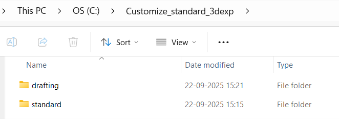
Step 1: Copy Default Drafting Standards

  • Navigate to the default installation directory:
  • C:\Program Files\Dassault Systèmes\B427_Cloud\win_b64\resources

(Note: The folder name (like B427_Cloud) might vary depending on your 3DEXPERIENCE version or deployment type)

  • Locate the folder named standard inside the resources directory.
  • Copy the entire “standard” folder and paste it into a new directory where you will store your custom standards.

Example: C:\Customize_standard_3dexp\standard

  • You can rename the folder or path based on your company’s configuration structure.


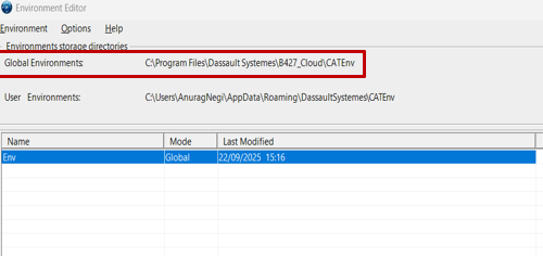
Step 2: Locate and Edit the CATENV File

The CATENV file defines environment variables and paths for 3DEXPERIENCE. Updating this file ensures your custom standards are recognized.

  • Open Environment Editor from the Windows Search bar
  • Locate the Global Environments section.
  • Identify where the CATENV file is stored, typically under:

C:\Program Files\Dassault Systemes\B427_Cloud\CATEnv

  • Open the CATENV file using Notepad++ or any text editor.
  • Find the line that specifies CATCollectionStandard (usually around line 29).
  • Add your custom standards folder path after the “=” sign.

Example: CATCollectionStandard=C:\Customize_standard_3dexp\standard

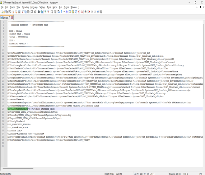
  • Save and close the file

Step 3: Open 3DEXPERIENCE and Configure Drafting Standards

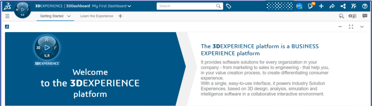
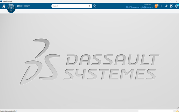
  1. Launch 3DEXPERIENCE and open any application.
  2. Close it immediately — this ensures environment paths refresh.
  3. It should be like below image


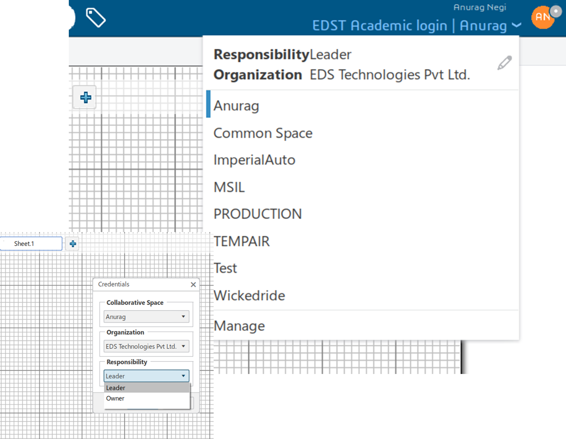
Step 4: Set Responsibility to “Owner”

  • Click the downward arrow next to your username.
  • Select EditResponsibility tab → change to Owner
  • Confirm the change.

(This step ensures you have permission to modify and save custom standards.)


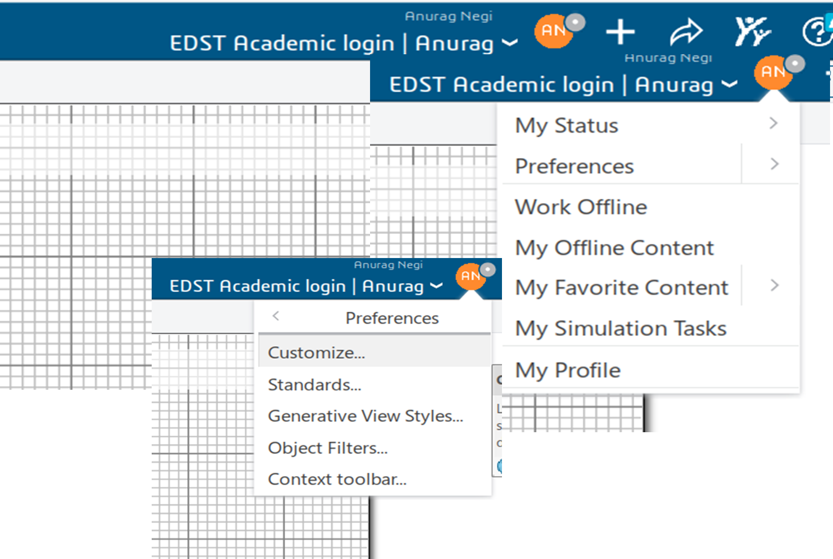
Step 5: Customize and Save Drafting Standard

  • In the App, click the “Me” symbol (beside your name).
  • Go to Preferences → Standards.
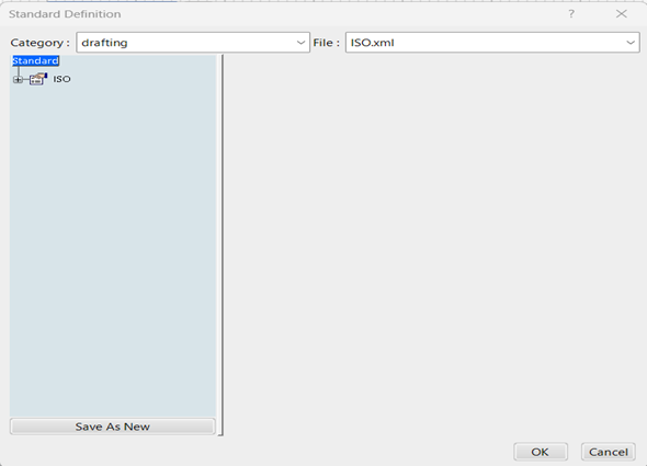
  • In the dialog box:
    • Set Category to “Drafting”.
    • Select the desired XML file (e.g., ISO.xml or ASME.xml).
    • Click Save As New and provide a new file name.
    • Save the file in your custom location:
    • C:\Customize_standard_3dexp\standard\drafting


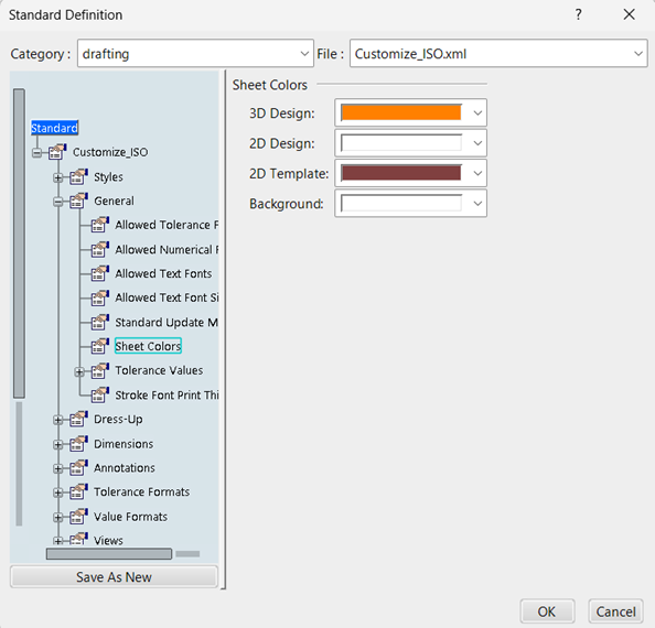
Step 6: Change Background Colour

Now that your custom standard is ready:

  • Navigate to:
    Standard → General → Sheet → Colors → 2D Template.
  • Choose your preferred background color.
  • Click OK to save.
  • Change the Responsibility back to Leader once completed.

You can now open any drawing to verify that the background color has successfully updated according to your preference.


Summary of Key Paths

Purpose Path
Default Standards C:\Program Files\Dassault Systemes\B427_Cloud\win_b64\resources\standard
Custom Standards C:\Customize_standard_3dexp\standard
CATENV File C:\Program Files\Dassault Systemes\B427_Cloud\CATEnv

Tips & Best Practices

  • Always backup the default standard before making modifications.
  • Keep a naming convention for your customized standards (e.g., ISO_Custom.xml).
  • Use version control if multiple engineers edit standards.
  • For large organizations, centralize the custom standard path to ensure consistency.

Conclusion

Changing the drafting background color in 3DEXPERIENCE isn’t just about aesthetics — it’s about improving readability, consistency, and user comfort. By following this guide, you can easily manage and customize your drafting environment using controlled standards and CATENV configurations.

Automatic Design: Precision Optimization for Peak Imaging System Performance

Design for any imaging system starts with a set of requirements such as focal length, field of view, image size and resolution. Selecting the appropriate first-order layout from the design library or sample lenses, closest to the specification is beneficial, yet it is often the simplest aspect of the design process. The initial design is plagued with various spherical and chromatic aberrations that degrade image quality and fails to account for any physical limitations or manufacturing tolerances. It is necessary to find a balance between meeting performance requirements and staying within budget. The primary challenge is to overcome the inherent trade-offs between these goals to achieve an optimal design that can be effectively implemented when coupled with physical constraints and manufacturing cost.

The anatomy of a lens is defined by how precisely the design is rectified to eliminate its intrinsic imperfections. The traditional method of correcting these flaws, a manual process of trial and error is extremely time consuming. Manipulation of several variables simultaneously, such as the curvature, thickness, or material of the lens, leads to the realization that correcting one aberration worsens another. This necessitates an endless cycle of design iterations which ultimately stagnates the product development cycle.


Fig. 1: Initial lens design in CODE V with both 2D and 3D views
 

Leveraging CODE V’s powerful optimization tool helps automate the task of finding the best design. This computational process combines image error data into a single value called the error function, that we attempt to make as small as possible. This thorough, iterative approach yields an imaging system that generates clear and distortion-free images. In addition to enhancing performance, it also improves overall efficiency and robustness.

Optimization: Paradigm Shift Towards Automation and Precision

CODE V’s optimization feature called Automatic Design (AUT) uses damped least square algorithm (DLS) to generate changes in variables that improve the system. Constraints defined based on physical dimension, material availability and manufacturing conditions act as boundaries when identifying the ideal solution.

Optimization Workflow in CODE V

  1. Define as variables all radii of curvatures, thickness values, and fictitious glasses in lens data manager (LDM).
  2. Make sure all glass elements are thick enough and glass index is not too high to ensure design is cost effective.
  3. Set specific constraints on parameters that shouldn’t be varied by the optimization process like, effective focal length (EFL), FOV, dimension or glass materials.
  4. Specify user defined error function or use the default spot size error function in CODE V.
  5. Draw the lens on each optimization cycle and analyze its modulation transfer function (MTF), point spread function (PSF) and various field aberration curves.
  6. Additionally, cost analysis evaluates the glass cost and blocking factors which helps compare relative costs of various design.
  7. Ghost and Narcissus image analysis (GHO, NAR) are paraxially based options for evaluating unwanted secondary images.


Fig.2: Depicts the optimization workflow in CODE V
 

Optimization tool is a necessity for modern optical design. It significantly reduces the time it takes to produce a manufacturable design thus enhancing efficiency. Drastically improves device performance and image quality due to its capability of simultaneously varying multiple parameters which is never possible manually. It helps ensure higher yield and lower costs by accounting for design sensitivity towards manufacturing.

In essence, optimization transforms the design process from a labor-intensive, trial-and-error approach into a data-driven, systematic search for the best possible solution.

Maximize Your 3DEXPERIENCE Usage: 5 Powerful Features to Try Today

The 3DEXPERIENCE platform by Dassault Systèmes is packed with powerful tools that help teams design, collaborate, simulate, and manage products more efficiently. While many users are familiar with the basic functions, there are several lesser-known features that can significantly improve productivity and collaboration – if you know where to look.

In this blog, we shall explore the top 5 features in 3DEXPERIENCE you might not be using – but should! Whether you’re an Engineer, Designer, Manager, or Project Coordinator, these tools can make your workflows faster, smarter, and more connected.


Bookmark Editor – Organize Your Data Like A Pro

Think of the Bookmark Editor as your personal project organizer within 3DEXPERIENCE. It helps you sort and manage your files, designs, and documents across different company projects – all in one place.

Why use it?
Instead of digging through folders or searching for file names, you can create bookmarks for quick access. It is perfect for managing product versions, project milestones, or different stages of development.

One of the useful tips is to use bookmarks to group project files and share them easily with your team – no more confusion about “latest versions.”


3DPlay – View and Share 3D Models Without CAD Software

With 3DPlay, you don’t need full CAD software to view, rotate, or inspect 3D models. It is a lightweight tool built into the platform that runs directly in your browser.

Why use it?
It allows stakeholders – including non-engineers – to interact with 3D models in real-time, without needing special software.

You can use 3DPlay to show designs to customers, management, or suppliers. It is a great way to communicate ideas visually.


Collaborative Tasks – Manage Work Visually

Forget sticky notes and disconnected task lists. The Collaborative Tasks app gives you a visual, drag-and-drop board to manage project work. It is like a digital Kanban board built right into 3DEXPERIENCE.

Why use it?
You can assign tasks, set deadlines, track progress, and attach files – all within your product development environment. You can create task boards for design reviews, approvals, or even daily team stand-ups.


Lifecycle Management – Control Your Product Data

One of the most powerful features of 3DEXPERIENCE is its built-in lifecycle management tools. They help you control who can see, edit, or approve your files at different stages – from concept to production.

Why use it?
You can lock designs, manage revisions, and control approvals – reducing the risk of errors and miscommunication. You can set up lifecycles for parts and assemblies to ensure that changes are reviewed and documented before they go live.


3DSwym – Collaborate Like a Social Network for Engineers

3DSwym brings a social-media-like experience to your engineering projects. It allows teams to post updates, ask questions, share ideas, and discuss challenges – all within the platform.

Why use it?
It improves communication across departments, especially for remote or cross-functional teams. You can create a 3DSwym community for each project or product line. It keeps conversations, ideas, and documents all in one place.


Conclusion

The 3DEXPERIENCE platform is much more than just a place to store CAD files – it is a complete ecosystem for collaboration, innovation, and efficient product development. By taking advantage of features like Bookmark Editor, 3DPlay, Collaborative Tasks, Lifecycle Management, and 3DSwym, your team can work smarter, stay better organized, and move faster from idea to execution.

Optimizing Manufacturing with DELMIA Factory Flow Simulation

Optimizing factory layouts, workflows, and material movement is essential for increasing productivity and cutting expenses in the fast-paced manufacturing sector of today. Manufacturers can digitally model, analyze, and optimize their manufacturing operations with Dassault Systèmes’ sophisticated DELMIA manufacturing Flow Simulation system. Before making tangible changes, companies can find inefficiencies, cut waste, and boost productivity by modelling manufacturing flows.

Efficiency and cost reduction are critical in the highly competitive manufacturing environment of today. Conventional production planning techniques can result in unforeseen bottlenecks, inefficiencies, and expensive operating expenses. Dassault Systèmes’ state-of-the-art DELMIA Factory Flow Simulation transforms production by offering a digital twin of factory activities.

Before adjusting in the real world, producers may use this potent tool to visualize, analyze, and optimize workforce dynamics, machine interactions, and material flow. Businesses may proactively detect inefficiencies, optimize production processes, and boost overall productivity by utilizing virtual simulation, which results in more intelligent, data-driven decision-making.


DELMIA Factory Flow Simulation: What is it?

DELMIA Factory Flow Simulation enables businesses to model and examine worker dynamics, machine interactions, and material flow in a digital twin of their plant. Without interfering with real production lines, this application offers insights into resource usage, process optimization, and logistics constraints.


DELMIA Factory Flow Simulation’s Salient Features

Modelling a virtual factory

  • Make a digital replica of the factory setting.
  • Workstations, robotic systems, AGVs, conveyors, and model machines.
  • Imagine how materials move and interact with one another.


Analysis of Material Flow

  • Logistics and inventory movement can be simulated and optimized.
  • Analyse storage and transportation procedures to eliminate bottlenecks.
  • Integrate real-time data to increase supply chain efficiency.


Optimization of Processes

  • Before making any physical alterations, consider various plant layout situations.
  • For increased efficiency, arrange workstations optimally.
  • Reduce cycle time and enhance assembly line balancing.


Workforce Planning and Resource Utilization

  • Optimize operator mobility and labour allocation.
  • Cut down on idle time and boost resource effectiveness.
  • Simulate possible risks and ergonomic issues to improve safety.


Integration of Real-Time Data and Performance Metrics

  • Create performance reports using key performance indicators (KPIs) as lead time, throughput, and utilization.
  • For dynamic simulation, integrate real-time production data with the Internet of Things.
  • To anticipate such interruptions, use predictive analytics.

Advantages of Factory Flow Simulation using DELMIA

More Effectiveness

  • Determine which activities don’t bring value and get rid of them.
  • Optimize workflow and cut down on material handling time.


Cost-Cutting

  • Optimize energy use, cut down on manufacturing delays, and minimize waste.
  • Reduce capital expenditure by remotely testing layouts and process enhancements.


Flexibility & Agility

  • Simulate several manufacturing situations in order to quickly adjust to changes in the market.
  • Analyse how new product launches affect manufacturing processes.
  • Improved ability to make decisions.
  • Insights based on data for planners and managers of factories.
  • Before implementing layout modifications, estimate their effects.

DELMIA Factory Flow Simulation Applications

  • Automotive & Aerospace: Streamline logistics and assembly lines in intricate production settings.
  • Industrial Equipment: Increase resource efficiency and machine utilization.
  • Electronics & Consumer Products: Simplify high-volume production procedures.
  • Logistics & Warehousing: Improve warehouse management and inventory flow.

Conclusion

For manufacturers looking to digitally optimize their industrial processes, DELMIA industrial Flow Simulation is revolutionary. Businesses may improve productivity, cut expenses, and streamline processes by utilizing virtual simulation, predictive analytics, and real-time data integration.

Understanding the Architecture of the 3DEXPERIENCE Platform

In today’s rapidly evolving engineering landscape, digital transformation often stalls when critical data like CAD files, simulation results, or change orders – reside in isolated silos. Dassault Systèmes’ 3DEXPERIENCE Platform addresses this challenge. It offers a unified, service-oriented foundation that spans the entire product lifecycle – from concept and design to manufacturing and after-sales.

In this post, we’ll break down the 3DEXPERIENCE architecture layer by layer, helping system architects, IT admins, and engineers understand how it scales, how it protects IP, and where to extend its capabilities.


High-Level Architecture: The Three-Tier Bedrock

At its core, the 3DEXPERIENCE platform is structured around a classic three-tier architecture:

  • Client Tier
  • Application Tier
  • Data Tier

While this model is familiar in IT, 3DEXPERIENCE tailors it for product lifecycle management (PLM) and real-time 3D collaboration, enabling each layer to evolve independently while supporting a seamless user experience.


Client Tier: UX Without Borders

The client tier ensures users can access the platform anytime, anywhere, using tools best suited for their role:

  • Web Top (Zero Footprint): Launch dashboards, BOM views, or tasks directly from a browser – no installations or plugins needed.
  • Rich Native Apps: Power users benefit from GPU-accelerated tools like CATIA, DELMIA, and SIMULIA.
  • Mobile Apps: Engineers can review 3D models, approve changes, or report issues from iOS/Android devices, even with limited bandwidth.
  • Unified Security: Whether on-site or remote, users go through a consistent SSO and TLS handshake, ensuring both convenience and security.


Application Tier: Microservices in Concert

The platform’s microservice architecture ensures modularity, scalability, and agility. Key services include:

Micro-service Core Duty Scale Strategy
3DSpace Manages PLM objects, lifecycles, and revisions Add nodes for metadata-heavy operations
3DSearch Provides full-text and semantic search Shard index clusters for high throughput
FCS/MCS Manages binaries and delta caching Geo-distributed for global performance
3DDashboard & Compass Widget shell and launcher for apps Stateless scale out freely
Workflow/Notification Automates tasks and notifications Horizontal scaling via JMS queues

All services are exposed via REST APIs, with SOAP and CAA options for legacy or deep integrations.


Data Tier: A Single Source of Truth

A strong data layer ensures data integrity and performance:

  • Metadata Layer: Backed by Oracle or PostgreSQL, supporting hundreds of object types and customizable schemas.
  • Vault Servers: Deduplicated, compressed file storage with efficient delta transfers.
  • Exalead Index: Enables faceted, semantic, and full-text search across metadata and file contents.
  • Resilience: Disaster recovery topologies replicate databases and file vaults across sites, while index clusters self-rehydrate.

Infrastructure & Deployment: Pick Your Cloud

Choose the right deployment model for your needs:

Model Footprint Best For
On-Premise Physical/ VM-based with self-managed stack Industries like aerospace with strict security needs
Private Cloud OpenShift/ Kubernetes Enterprises needing elasticity with control
SaaS/ 3DEXPERIENCE Works Fully managed by Dassault Systèmes SMBs preferring simplicity and low overhead

Regardless of mode, all setups use Apache TomEE, reverse proxies, and sticky session load-balancers enabling smooth migration between models.


Security: Trust by Design

Security is deeply integrated into every layer:

  • Authentication: Supports SAML, Kerberos, LDAP, and OAuth2.
  • Authorization: Contextual RBAC for example, suppliers can download STEP files but not native CAD.
  • Encryption: TLS 1.3 in transit, with optional AES-256 at rest.
  • Audit Logging: Immutable records for all object events ensure compliance.


Extensibility: From No-Code to Full-Code

Whether you’re a business analyst or a hardcore developer, there’s a way to customize the platform:

  • CAA V6 SDK: Extend the platform with C++/Java add custom menus, commands, or background services.
  • EKL (Engineering Knowledge Language): Create design rules, validation checks, and automation scripts.
  • REST Widgets: Build JavaScript-based mashups that integrate PLM data with tools like Jira, SAP, or IIoT.
  • Business Process Templates: Drag-and-drop editor for change workflows—no code required.

Why This Architecture Matters

Benefit Impact
Unified Data Eliminates duplication across BOMs, CAD files, and workflows
Real-Time Collaboration Teams across continents work on the same model in real time
Elastic Scalability Add compute or storage nodes without disruption
Defense-Grade Security Meets compliance without expensive rewrites
Lower TCO One platform replaces multiple disconnected systems

Conclusion

The 3DEXPERIENCE Platform isn’t just a set of tools – it’s an ecosystem built on a robust, scalable, and secure architecture. By understanding its layered design – from clients and services to data and extensibility – you’re better equipped to deploy it strategically, customize it safely, and grow it alongside your innovation goals.

Transforming Product Design and Engineering with AI

In today’s competitive environment, engineering and product design are no longer about creating a single feasible solution. Instead, they demand continuous innovation, rapid iteration, and smarter decision-making. Enterprises are under immense pressure to:

  • Deliver innovative products faster.
  • Reduce costs while maintaining high performance.
  • Ensure sustainability and compliance with evolving global standards.


Dassault Systèmes, through its 3DEXPERIENCE platform and CATIA application, is at the forefront of this transformation. By embedding Artificial Intelligence (AI) and Generative Design into its digital engineering solutions, Dassault is creating what it calls AI-Driven Generative Experiences – a paradigm shift that reshapes the entire product lifecycle.

This is not just about automation – it’s about empowering engineers with machine learning, deep learning, and knowledge-driven design intelligence to achieve what was previously impossible: smarter, lighter, faster, and more sustainable designs.


AI in Dassault Systèmes Solutions

Dassault Systèmes has already infused AI into multiple areas of its product ecosystem. Today, users experience AI-driven workflows in conceptual design, engineering, manufacturing, and lifecycle management.


Generative Design with CATIA

  • CATIA Generative Design harnesses AI to automatically create design alternatives that meet functional, structural, and aesthetic requirements.
  • Instead of manually modeling each iteration, engineers define the design intent, performance goals, and constraints, and CATIA’s AI explores thousands of solutions in minutes.
  • For example, in aerospace and automotive, generative design has enabled lightweight structural components that reduce material use by 30–50% while maintaining safety.


Knowledge-Based Engineering (KBE) with AI Support

  • CATIA captures industry-specific rules and corporate best practices so that engineers don’t reinvent the wheel.
  • AI enhances this by learning from previous projects, recognizing patterns, and ensuring compliance with industry regulations (aerospace, medical devices, automotive, etc.).
  • This not only improves reusability but also reduces costly design errors.

AI-Powered Simulation with SIMULIA

  • SIMULIA accelerates finite element analysis (FEA) and computational fluid dynamics (CFD) by integrating AI-based algorithms.
  • Simulations that once required hours or days are now optimized with AI models trained on previous runs.
  • Engineers can quickly predict the outcome of new designs with high accuracy – leading to faster iteration cycles and fewer physical prototypes.


Predictive Maintenance & Virtual Twin

  • Dassault’s Virtual Twin Experience combines IoT data with AI models to simulate real-world product behavior.
  • By predicting wear, fatigue, or system failures before they occur, manufacturers save on downtime and warranty costs.
  • For instance, in the energy sector, AI-powered virtual twin is used to optimize wind turbine operations, extending asset life and efficiency.


Automation in Drafting & Modeling

  • AI recognizes features, standard components, and patterns, automating repetitive tasks in 2D drafting and 3D modeling.
  • For example, hole placement, rib creation, or tolerance checks can now be completed automatically, enabling engineers to focus on innovation rather than routine tasks.

Benefits/ Advantages for Users

Organizations using Dassault Systèmes solutions with AI integration already enjoy quantifiable benefits:

  • Faster Time-to-Market: Development cycles are reduced by up to 300% through automated iterations and optimized workflows.
  • Superior Product Performance: Generative design enables lighter, stronger, and more efficient components, especially for industries like aerospace, automotive, and industrial equipment.
  • Reduced Costs: Standardized design reuse (up to 80%) cuts engineering effort. Predictive maintenance reduces warranty costs by 10% or more.
  • Smarter Decision-Making: AI analyzes complex datasets (design, manufacturing, and operational data) to provide actionable insights, helping engineers make evidence-based decisions.
  • Seamless Collaboration: AI tools integrated into the 3DEXPERIENCE platform allow cross-functional collaboration across design, simulation, and manufacturing teams – ensuring traceability and consistency.

The Future of Design with Dassault Systèmes

The next wave of AI in Dassault Systèmes’ ecosystem will go beyond assistance – it will transform human-AI collaboration in engineering.

Hyper-Automated Design

  • Design tasks like meshing, tolerance checks, and compliance verification will become fully automated.
  • Engineers will move from “creating geometry” to orchestrating AI-driven workflows.

Generative AI as a Design Co-Pilot

  • AI will act like a partner, proposing optimized concepts, guiding trade-off decisions, and predicting how a design will perform across different scenarios.
  • Example: An AI co-pilot could suggest alternative materials based on cost, availability, and sustainability goals in real-time.

Sustainable Design by Default

  • Dassault’s future AI will prioritize eco-friendly materials, energy efficiency, and recyclability.
  • Every design recommendation will be scored not just on cost and performance but also on environmental impact, aligning with circular economy principles.

Self-Optimizing Virtual Twins

  • The next evolution of Virtual Twins will integrate real-time IoT feedback with AI that can self-correct and self-optimize.
  • This means products won’t just be simulated – they will continuously learn and improve throughout their lifecycle.

Natural Language & Voice Interfaces

  • Engineers will be able to interact with CATIA and SIMULIA using natural language commands (e.g., “Generate the lightest bracket design that can withstand 500N load”).
  • AI will make design tools as intuitive as conversing with a colleague.

Conclusion

AI is no longer a future promise – it is already embedded within Dassault Systèmes’ solutions, delivering value across industries today.

  • Generative Design accelerates innovation.
  • AI-powered Simulation reduces risks and costs.
  • Virtual Twins bring predictive intelligence into operations.
  • Automation eliminates repetitive work, freeing engineers for creativity.


As AI evolves, Dassault Systèmes will push the boundaries further with self-optimizing systems, eco-driven design intelligence, and AI-human co-creation environments.

For engineers, designers, and enterprises, this means smarter innovation, faster delivery and sustainable growth. The future of design is AI-driven, generative, and collaborative. With Dassault Systèmes, that future starts today.

Subscribe to our newsletter

Get all the latest information on Events, Sales and Offers.