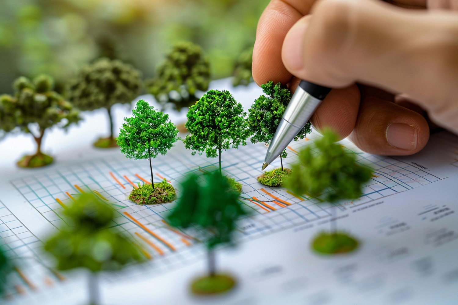
According to the India State of Forest Report (ISFR) 2021, released by the Ministry of Environment, Forests, and Climate Change, India’s total forest area constitutes 21.71% of the country’s geographical area, while the tree cover is estimated to be 2.91%. Consequently, the combined coverage of forests and trees accounts for 24.62% of the nation’s geographical area. Geographic Information Systems (GIS) have emerged as a cornerstone for effective forest management and conservation. By integrating diverse datasets and offering sophisticated spatial analysis tools, GIS empowers foresters, ecologists, and conservationists to make data-driven decisions, optimize resource allocation, and effectively address pressing environmental concerns.
Mapping Forest Resources
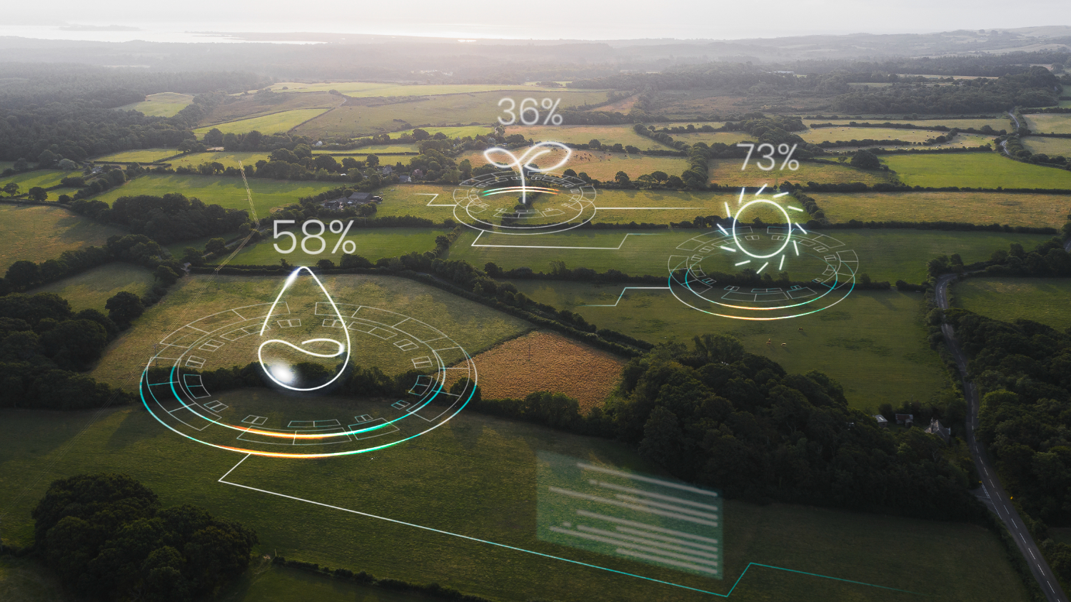
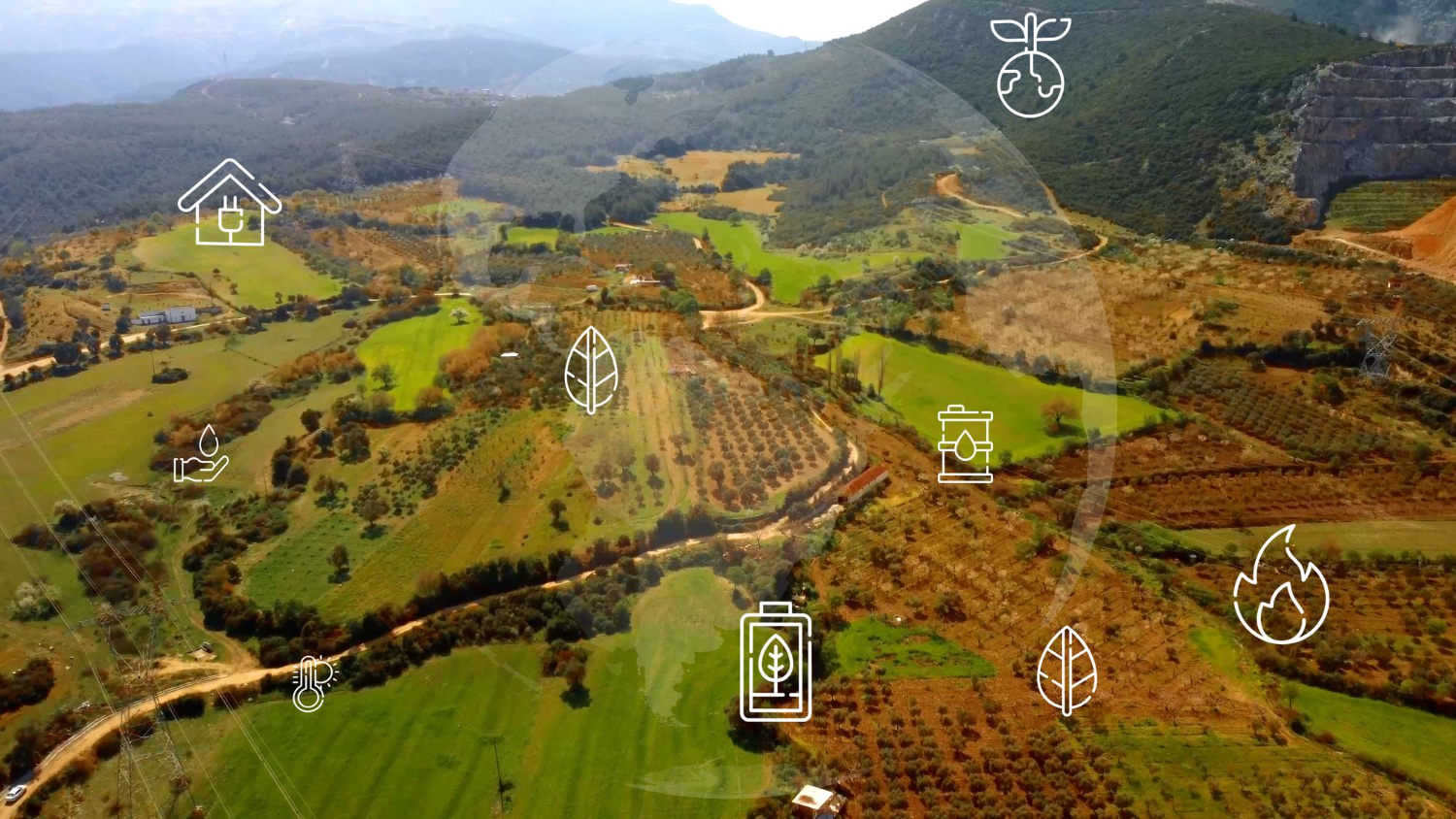
GIS plays a crucial role in generating comprehensive maps that provide detailed insights into forest composition, structure, and ecological health. High-resolution satellite imagery and aerial surveys are integrated within GIS platforms to produce accurate and up-to-date forest maps. These maps enable forest managers to effectively monitor changes in forest cover over time, such as deforestation, forest degradation, and the impacts of natural disturbances like wildfires and storms.
Forest Planning and Management
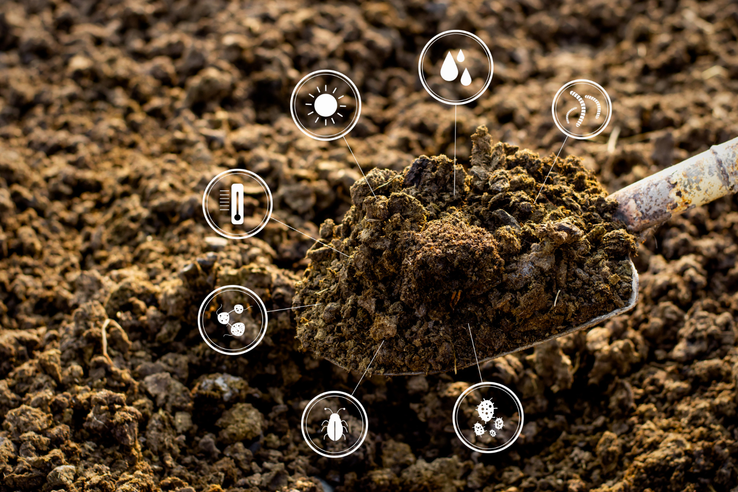
Regular updates and revisions are essential to sustain forest preservation efforts and enhance green cover. The forest department leverages GIS and remote sensing technologies to improve its capabilities by providing critical input data such as forest density, forest type, and land resources. Additionally, GIS enables the inclusion of maps detailing road networks, settlements, and water bodies, facilitating the design of efficient management strategies.
Wildfire Risk Assessment and Management
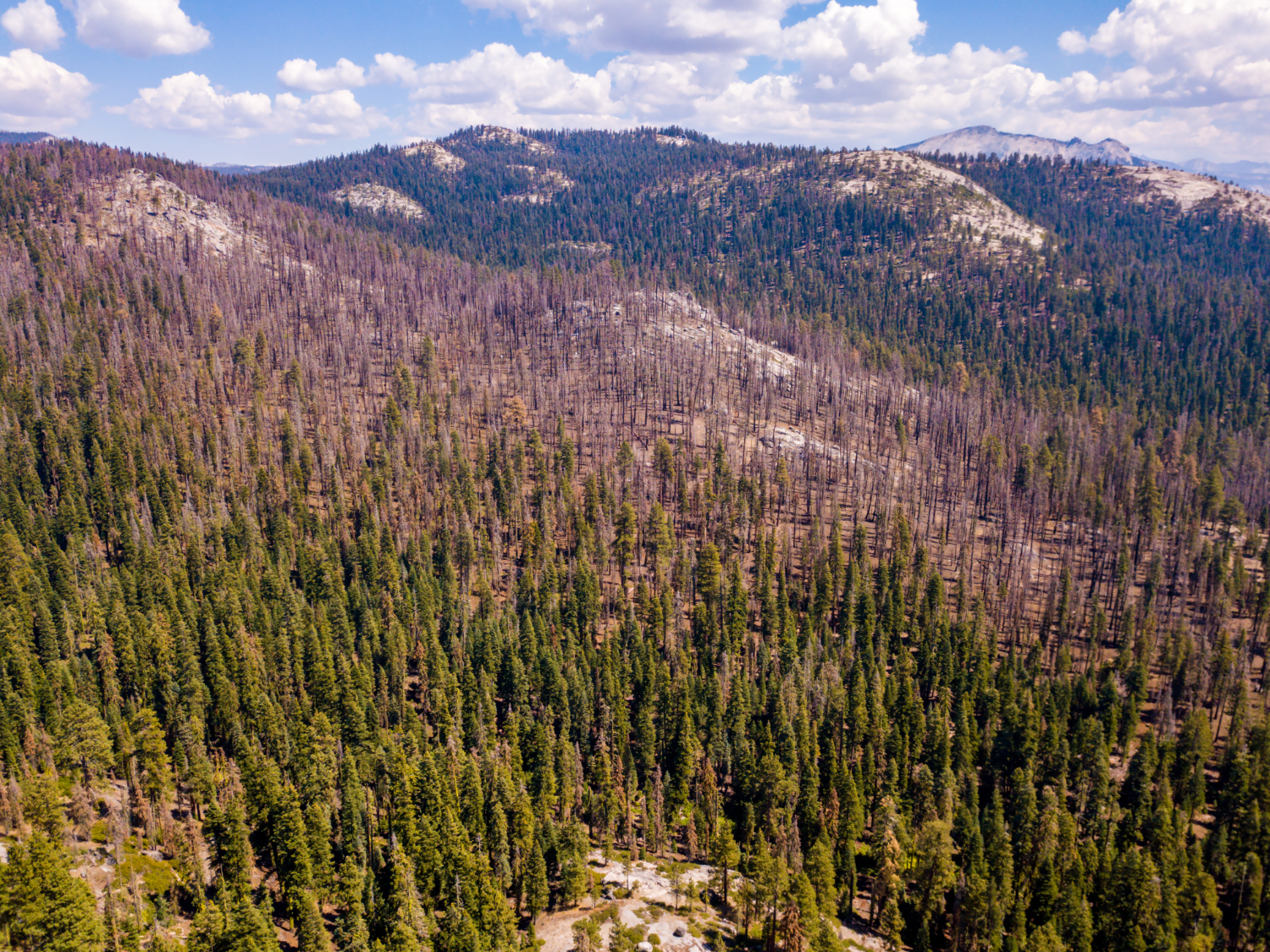
Wildfires pose a substantial threat to forest ecosystems worldwide. GIS serves as an invaluable tool for effective wildfire management by providing real-time data on fire behavior, prevailing weather conditions, and fuel availability. This critical information supports accurate predictions of fire spread, facilitates the planning and execution of fire suppression activities, and enables the strategic design of firebreaks. Furthermore, post-fire analysis conducted within a GIS environment assists in assessing the extent of damage and developing comprehensive restoration plans.
Forest Management
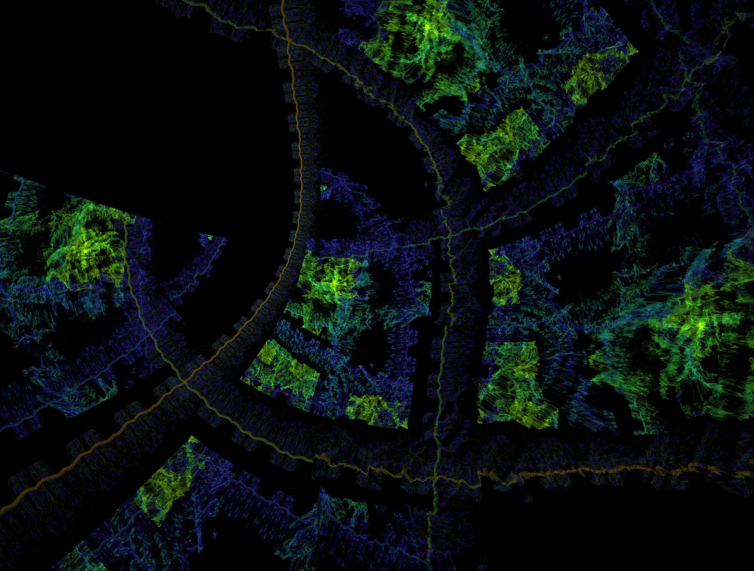
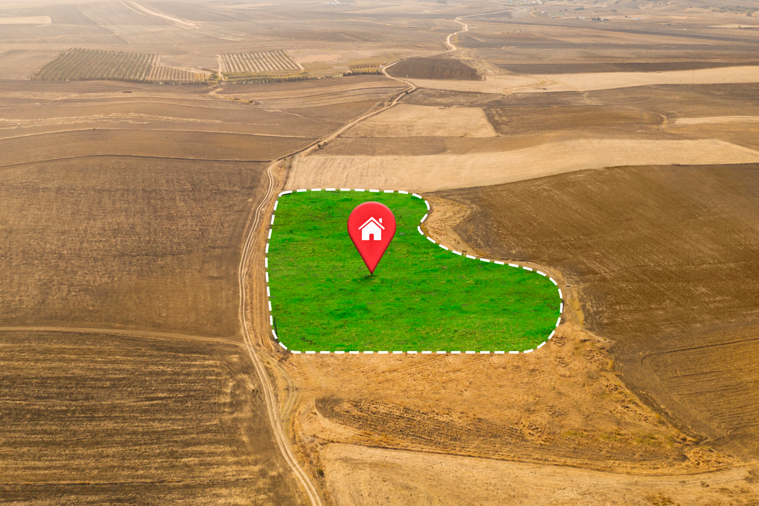
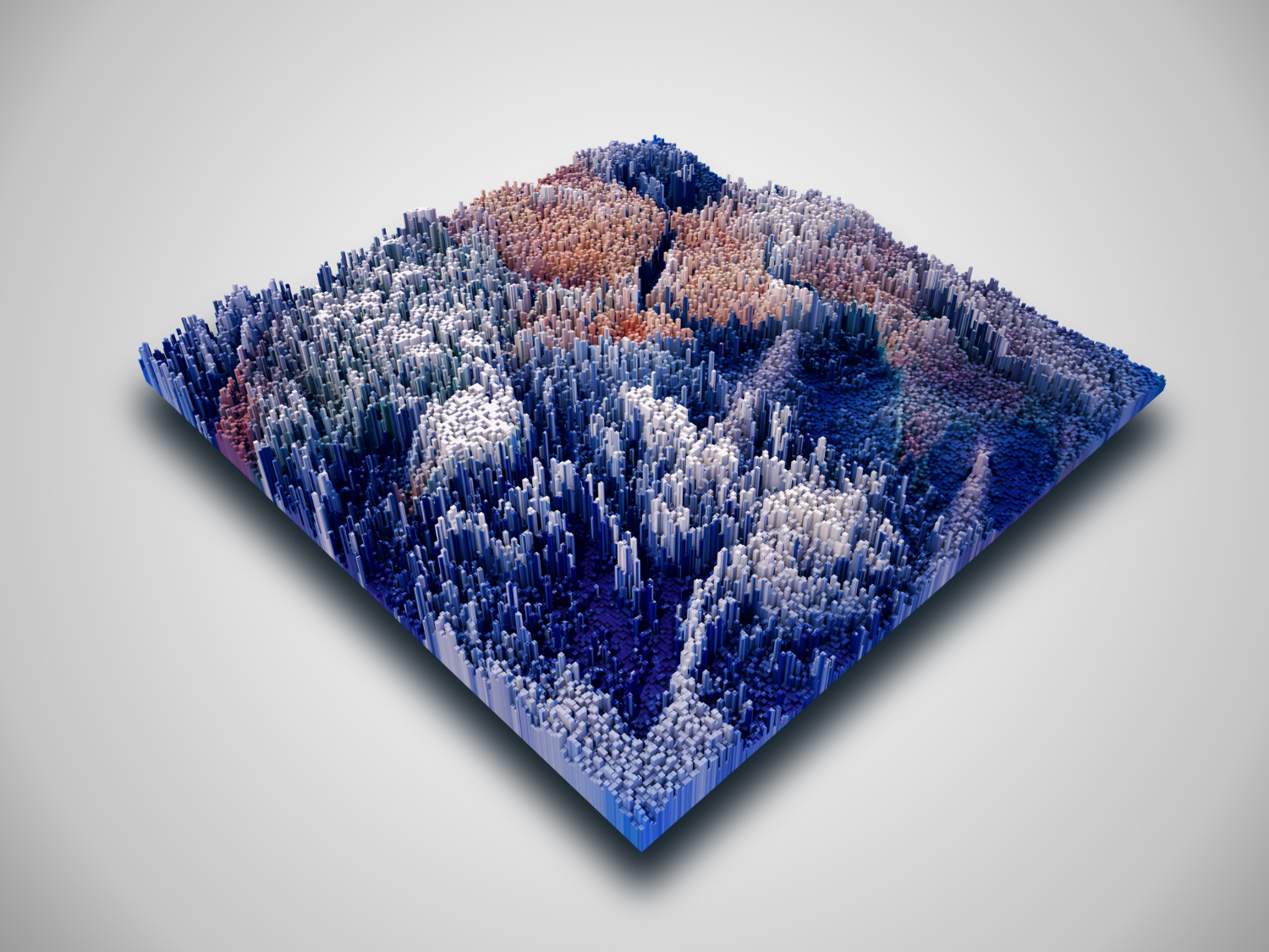
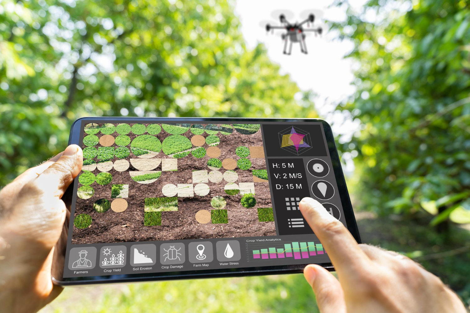
GIS and Remote Sensing technologies are essential for effective forest monitoring, allowing for the creation of detailed, digital maps of forests with irregular boundaries. Periodic updates provide accurate insights into forest changes, supporting the development of sustainable management strategies and disaster mitigation plans. Advanced satellite and drone imagery, along with techniques like False Colour Composite (FCC) and True Colour Composite (TCC), enable precise monitoring of forest coverage, with FCC enhancing features not visible to the human eye, aiding in the detection of forest cover changes.
Habitat Mapping and Biodiversity Conservation
Forests serve as vital habitats for a diverse array of flora and fauna. GIS plays a pivotal role in habitat mapping and biodiversity conservation by enabling the identification of critical habitats and biodiversity hotspots. Through spatial analysis, GIS facilitates the assessment of habitat fragmentation, connectivity, and the impact of human activities on wildlife populations. This valuable information empowers conservationists to effectively design and implement protected areas, establish wildlife corridors, and develop comprehensive management plans that safeguard biodiversity.
Conclusion
The integration of GIS in forestry has transformed the way forests are managed and conserved. From mapping and monitoring, planning to disaster management, GIS provides the tools and insights necessary for sustainable forest management. As technology continues to advance, the role of GIS in forestry will only become more critical, helping us protect and preserve our valuable forest ecosystems for future generations.
By leveraging the power of GIS, we can ensure that our forests remain healthy, resilient, and productive, supporting biodiversity and providing essential ecosystem services.