In the ever-evolving realm of engineering simulation, the need for sophisticated tools that automate and optimize the design process has reached a crucial point. SIMULIA Isight from Dassault Systèmes is a potent simulation process automation and design optimization software. This blog post unfolds a strategic walkthrough, unraveling the indispensable steps to harness Isight’s prowess for impactful data analysis in engineering projects.
Defining the Simulation Process
It starts with meticulously evaluating the engineering objectives. Then, identify the specific simulations or analyses that Isight will automate or optimize.Understanding stress analysis, fluid flow simulation, and thermal studies is crucial for a successful workflow using SIMULIA Isight. Understanding stress analysis, fluid flow simulation, and thermal studies is crucial for a successful workflow using SIMULIA Isight.This can be demonstrated through a complex engineering problem involving hyperelastic materials such as a rubber bush, highlighting an optimization-based approach using parametric data analysis with Isight.
Integrating Simulation Tools
Isight excels at integrating various simulation tools seamlessly into one unified environment. By establishing connections with specific tools such as Abaqus or other third-party software, this integration ensures a cohesive workflow. It enables smooth data transfer between these tools, ultimately boosting efficiency and accuracy in the overall process.
Creating a Workflow
Creating a logical workflow is key to making the most of Isight.This includes outlining the precise sequence Isight will follow to execute simulations seamlessly. It encompasses detailing the transfer of input information among various simulation tools to establish a streamlined and automated simulation procedure. Isight’s intuitive interface facilitates the visual design of workflows, making it accessible to both seasoned engineers and those new to simulation process automation.
Case Studies: Hyperelastic Material
Hyperelastic materials, also termed green elastic materials, possess the unique ability to undergo significant elastic deformations and revert to their original shape upon load removal. These materials, often described using a strain-energy density function like the neo-Hookean model, are used in fields such as biomechanics, rubber-like substances, and the mechanics of soft tissues.In engineering simulations, accurately modelling hyperelastic materials is vital for predicting responses to large deformations, making tools like Isight crucial for design optimization and simulation automation involving such materials.
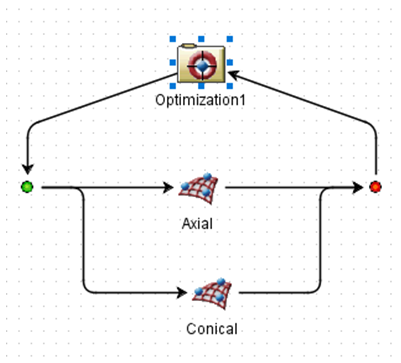
Step 1: A parametric file was crafted in Abaqus, followed by analyses under diverse loading conditions such as axial, radial, conical, and torsional loads. All associated files, including CAE and ODB files, were consolidated in a single folder.
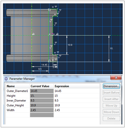
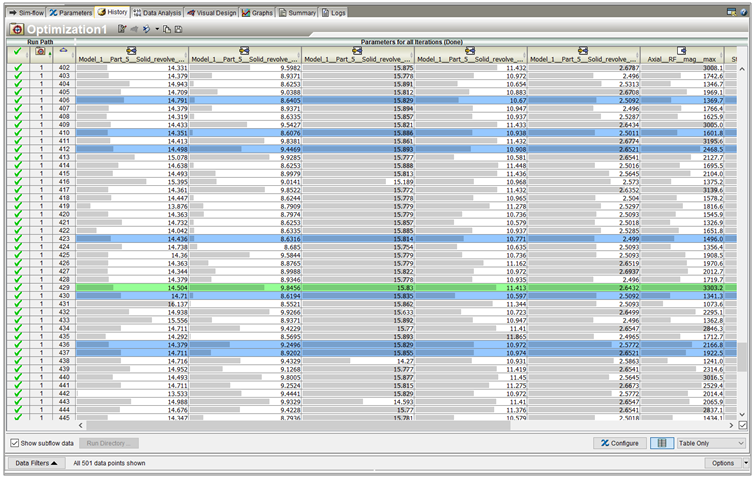
Step 2: Defining Design Variables – In projects geared towards optimization, pinpoint the design variables that Isight will manipulate to achieve desired outcomes. These variables could include material properties, geometric parameters, or any other factors influencing your simulation. Set constraints and allowable ranges, guiding Isight in its optimization process. In our case, geometrical parameters were defined rather than material inputs, as illustrated in the below snapshot of the DOE Editor windows with parameters defined.
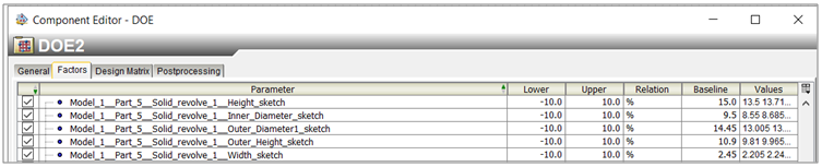
Step 3: Setting Up Design of Experiments (DOE) – Efficiently navigate the parameter space by definingDesign of Experiments. Isight helps by letting you systematically change input values to check many scenarios.You can specify the number of simulations and the range of values for each variable, enabling Isight to navigate the design space. Different components can be aligned either parallelly or in series for data flow and execution. In our methodology, two Abaqus components were utilized for different loading conditions and physics, and Isight performed the Design of Experiment using optimal Latin hypercube methodology.
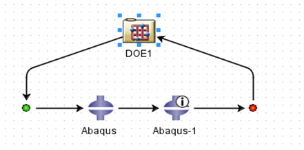
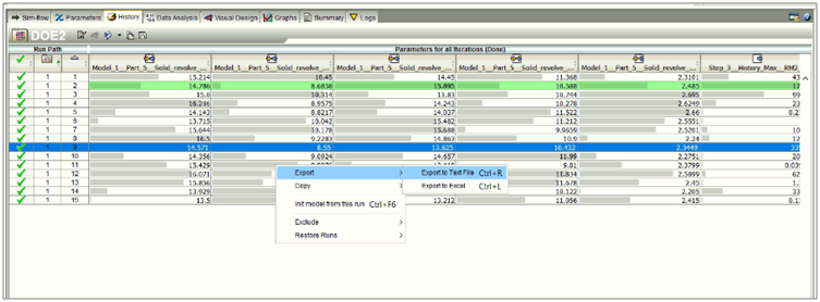
Step 4: Running Simulations – Withmeticulously designed workflow in place, execute the Isight workflow and witness the seamless automation unfold. Isight automates simulations with specified parameters, saving valuable time and reducing the likelihood of manual errors. Once the DOE Study is complete, all the results can be saved and further utilized for approximation studies.
Step 5: Analyzing Results
Upon completion of simulations, Isight equips engineers with robust tools for result analysis. They can visualize data, generate plots, and extract meaningful insights from the simulation results. Isight’s post-processing capabilities empower engineers to delve deep into the system’s behaviour and performance.
Step 6: Optimization
For projects focused on optimization, Isight automatically adjusts design variables to meet predefined objectives. Results can be reviewed, improvements can be assessed and iterated further if necessary.
Step 7: Iterate and Refine
Isight’s flexibility allows for iterative refinement, enabling engineers to progressively enhance their simulation process.
Step 8: Documentation and Reporting
A step often overlooked is comprehensive documentation. Isight enables the generation of detailed reports covering the simulation process, results, and any optimizations achieved. These reports serve as invaluable resources for communication with project stakeholders, offering a clear overview of the analysis methodology and outcomes.
By following these steps, unlock the full power of Isight, automating and optimizing your engineering simulations. This, in turn, drives efficiency and innovation in your projects. Stay tuned for more insights into the evolving landscape of simulation technology.