Extended Simulation of Wind Turbines Using ABAQUS
- Varun Sharma
- December 25, 2024
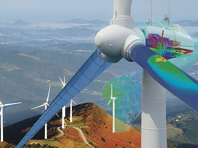
Wind turbines are pivotal in the global transition towards renewable energy systems. Accurate simulation of wind turbines using advanced finite element analysis (FEA) tools like ABAQUS enables engineers to design more efficient, reliable, and durable systems. In this blog, we will delve into the process of simulating wind turbines using ABAQUS, focusing on structural, aerodynamic, and fatigue analyses.
Key Components of Wind Turbine Simulation
- Blade Analysis: Wind turbine blades endure complex loads, including aerodynamic forces, gravitational effects, and centrifugal forces. ABAQUS’ advanced material modeling capabilities are ideal for analyzing composite blades.
- Tower Structure: The tower must withstand wind loads and dynamic effects from the rotor. Structural stability under cyclic loads is crucial.
- Rotor-Nacelle Assembly: This component converts wind energy into mechanical energy. Simulation focuses on the interaction between rotating parts and the structural housing.
- Foundation: The foundation supports the entire structure, transferring loads to the ground. Soil-structure interaction plays a key role in ensuring stability.
Extended Steps for Wind Turbine Simulation
- Geometry Creation:
- Create the geometry of the wind turbine using CAD software or directly in ABAQUS/CAE. This includes the blade, tower, rotor, nacelle, and foundation.
- The geometry should represent real-world conditions, incorporating precise measurements and aerodynamic designs.
- Material Properties:
- Assign material properties for each component. For example:
- Blades: Composite materials (e.g., carbon fiber reinforced polymers).
- Tower: Steel or other high-strength alloys.
- Foundation: Concrete or reinforced concrete
- Meshing:
- Generate a fine mesh for accurate results, particularly for critical regions like blade edges and tower connections.
- Use hexahedral elements for simpler shapes and tetrahedral elements for complex geometries.
- Perform mesh convergence studies to ensure solution accuracy.
- Boundary Conditions:
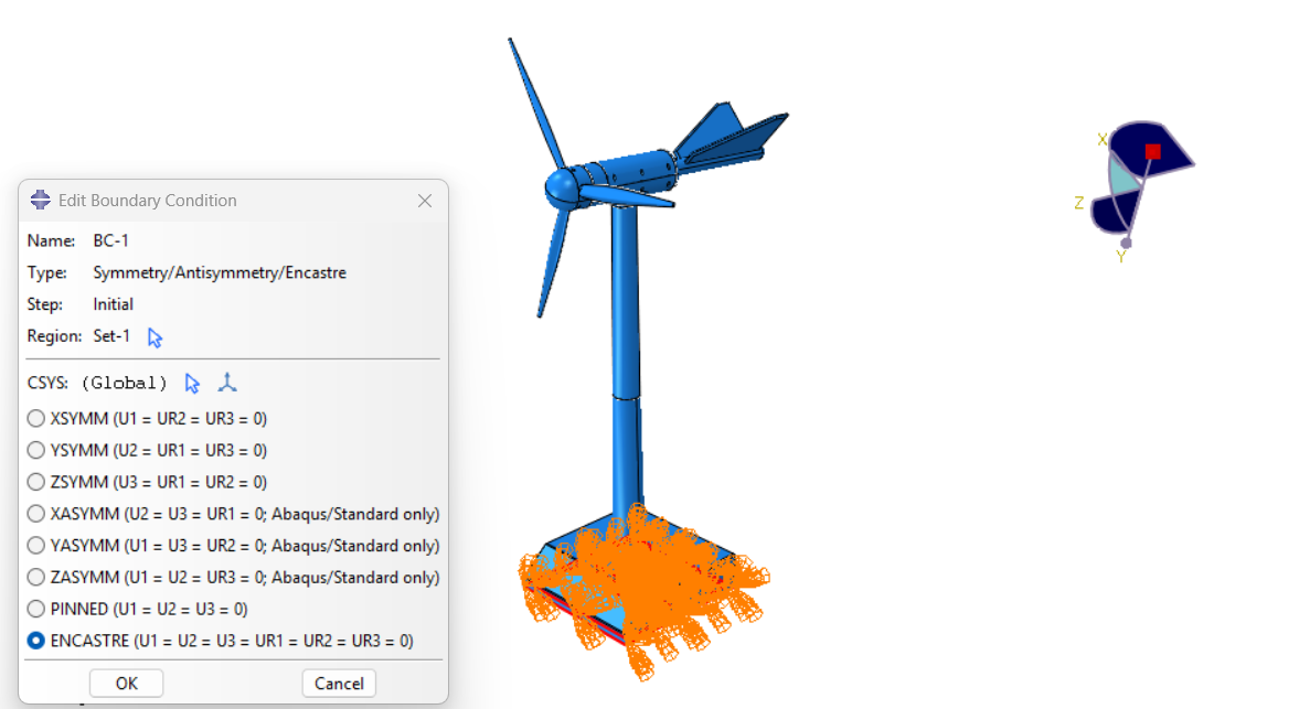
- Fix the base of the tower to represent its connection to the foundation.
- Apply wind loads along the length of the blades and lateral forces on the tower.
- Include gravity and centrifugal forces for realistic loading conditions.
- Load Cases:
- Static Loads: Simulate constant wind conditions for structural stability analysis.
- Dynamic Loads: Use time-varying wind loads for transient and fatigue analysis.
- Extreme Events: Model conditions such as gusts or shutdown scenarios.
- Analysis Setup:
- Use the Static General step for structural integrity checks under steady loads.
- For time-dependent studies, employ the Explicit Dynamics or Implicit Dynamics solver.
- Include non-linear effects such as large deformations and material plasticity for blades and tower sections.
- Post-Processing:
- Use ABAQUS/CAE’s visualization module to evaluate stress distribution, deformation, and vibration modes.
- Identify critical regions for design improvement, such as areas with high stress concentrations.
Case Study: Blade Deformation
Objective:
To evaluate the deformation of a wind turbine blade under cyclic aerodynamic loads.
Steps:
- Modeling: The blade was modeled with composite layups to represent real-world manufacturing processes.
- Loading: A cyclic wind load was applied over 1,000 load cycles.
Results:
- Stress concentrations were observed at the root of the blade.
- The fatigue analysis highlighted a potential failure region, prompting geometry and material modifications.
INP File for Blade Analysis
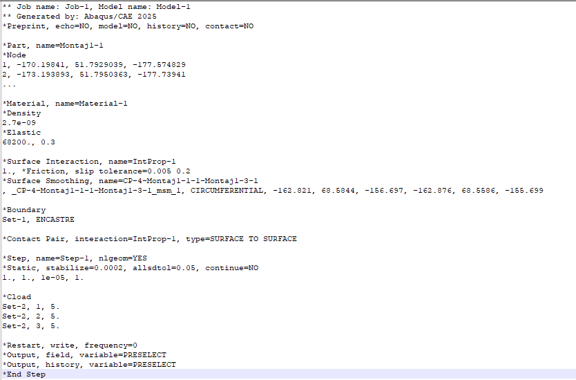
Below is an example of a basic INP file setup for wind turbine blade analysis:
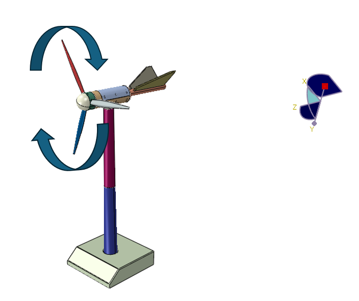
CAD, Meshed, and Result Images
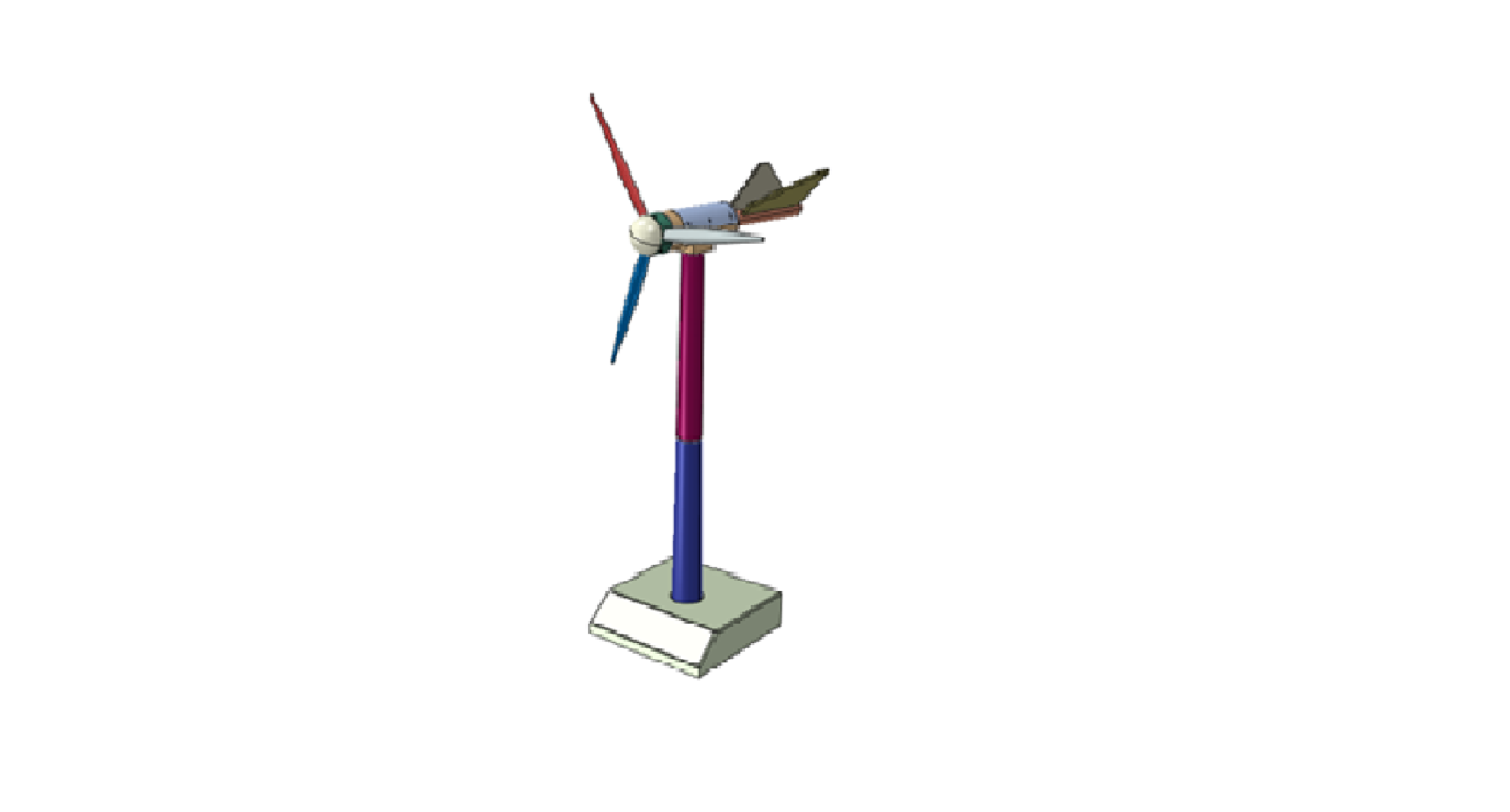
- CAD Model of the Wind Turbine:
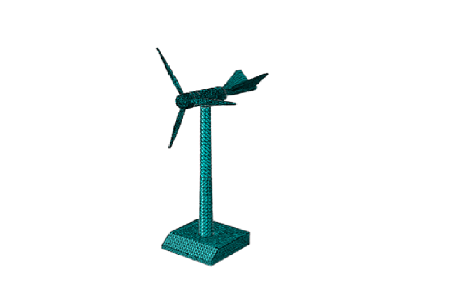
- Meshed Model:
Conclusion
Simulating wind turbines in ABAQUS enables engineers to refine designs for efficiency and reliability. With detailed CAD models, accurate meshing, and comprehensive analysis, engineers can optimize turbine performance and reduce failure risks. Leveraging tools like ABAQUS for wind turbine simulation is a step towards achieving a sustainable energy future.

- Varun Sharma
- December 25, 2024
Extended Simulation of Wind Turbines Using ABAQUS
Wind turbines are pivotal in the global transition towards renewable energy systems. Accurate simulation of wind turbines using advanced finite element analysis (FEA) tools like ABAQUS enables engineers to design more efficient, reliable, and durable systems. In this blog, we will delve into the process of simulating wind turbines using ABAQUS, focusing on structural, aerodynamic, and fatigue analyses.
Key Components of Wind Turbine Simulation
- Blade Analysis: Wind turbine blades endure complex loads, including aerodynamic forces, gravitational effects, and centrifugal forces. ABAQUS’ advanced material modeling capabilities are ideal for analyzing composite blades.
- Tower Structure: The tower must withstand wind loads and dynamic effects from the rotor. Structural stability under cyclic loads is crucial.
- Rotor-Nacelle Assembly: This component converts wind energy into mechanical energy. Simulation focuses on the interaction between rotating parts and the structural housing.
- Foundation: The foundation supports the entire structure, transferring loads to the ground. Soil-structure interaction plays a key role in ensuring stability.
Extended Steps for Wind Turbine Simulation
- Geometry Creation:
- Create the geometry of the wind turbine using CAD software or directly in ABAQUS/CAE. This includes the blade, tower, rotor, nacelle, and foundation.
- The geometry should represent real-world conditions, incorporating precise measurements and aerodynamic designs.
- Material Properties:
- Assign material properties for each component. For example:
- Blades: Composite materials (e.g., carbon fiber reinforced polymers).
- Tower: Steel or other high-strength alloys.
- Foundation: Concrete or reinforced concrete
- Meshing:
- Generate a fine mesh for accurate results, particularly for critical regions like blade edges and tower connections.
- Use hexahedral elements for simpler shapes and tetrahedral elements for complex geometries.
- Perform mesh convergence studies to ensure solution accuracy.
- Boundary Conditions:
- Fix the base of the tower to represent its connection to the foundation.
- Apply wind loads along the length of the blades and lateral forces on the tower.
- Include gravity and centrifugal forces for realistic loading conditions.
- Load Cases:
- Static Loads: Simulate constant wind conditions for structural stability analysis.
- Dynamic Loads: Use time-varying wind loads for transient and fatigue analysis.
- Extreme Events: Model conditions such as gusts or shutdown scenarios.
- Analysis Setup:
- Use the Static General step for structural integrity checks under steady loads.
- For time-dependent studies, employ the Explicit Dynamics or Implicit Dynamics solver.
- Include non-linear effects such as large deformations and material plasticity for blades and tower sections.
- Post-Processing:
- Use ABAQUS/CAE’s visualization module to evaluate stress distribution, deformation, and vibration modes.
- Identify critical regions for design improvement, such as areas with high stress concentrations.
Case Study: Blade Deformation
Objective:
To evaluate the deformation of a wind turbine blade under cyclic aerodynamic loads.
Steps:
- Modeling: The blade was modeled with composite layups to represent real-world manufacturing processes.
- Loading: A cyclic wind load was applied over 1,000 load cycles.
Results:
- Stress concentrations were observed at the root of the blade.
- The fatigue analysis highlighted a potential failure region, prompting geometry and material modifications.
INP File for Blade Analysis
Below is an example of a basic INP file setup for wind turbine blade analysis:

CAD, Meshed, and Result Images
- CAD Model of the Wind Turbine:

- Meshed Model:


Conclusion
Simulating wind turbines in ABAQUS enables engineers to refine designs for efficiency and reliability. With detailed CAD models, accurate meshing, and comprehensive analysis, engineers can optimize turbine performance and reduce failure risks. Leveraging tools like ABAQUS for wind turbine simulation is a step towards achieving a sustainable energy future.
