Parametric Modelling in CATIA V5
The dimensions in a 3D Model have some relationships or interconnections with each other in Parametric Modelling in CATIA V5. If any one of the dimensions is changed in 3D Model, then all other dimensions will also change in the specified ratio.
Key tools used in Parametric Modelling are:
- Parameters
- Formulas
- Design Table
Parameters
Parameters are the characteristics that control different aspects of geometry and features. Parameters could be of different types such as Length, Area, Mass, Boolean and many more.
Parameters are of two categories:
- Intrinsic Parameters:
Intrinsic Parameters are created automatically as we create the geometries and features in CATIA V5.
- User Parameters:
In Parametric Modelling, the Parameters which user creates for controlling the dimensions and features are called User Parameters.
Formulas
Formulas are the relations between different geometrical entities and parameters. For example, to have Inner Diameter as half of Outer Diameter, a formula can be created as:
Inner Diameter = 0.5 * Outer Diameter.
Design Table
Design Table is a text or .csv (Excel) file which contains different set of input values for parameters called configurations. For example, a company has five variants of a product. A design table can be created in which five configurations of input values of parameters can be entered. Selecting each configuration from design table will result in a different variant of the product.
Steps in Parametric Modelling:
- Create 3D Model:
Create the 3D Model as per the drawing provided using different workbenches like Sketcher, Part Design etc. In the below image, a tumbler is modelled. The features used in this tumbler are Pad, Pocket and Edge Fillet.
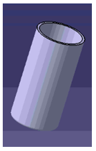
Now, design intent is to design a tumbler in which the same ratio is maintained for all the other geometrical features for any value of outer diameter of tumbler.
- Create Parameters:
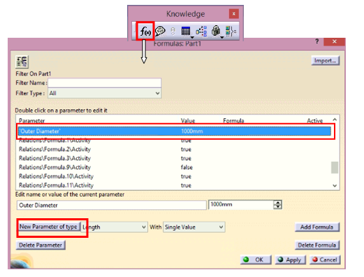
Create Parameters for input dimensions. For example, in this tumbler there is only one input parameter i.e., Outer Diameter and rest of the dimensions will automatically get adjusted as per the Outer Diameter. Hence, a Parameter of “length” type named Outer Diameter is created.
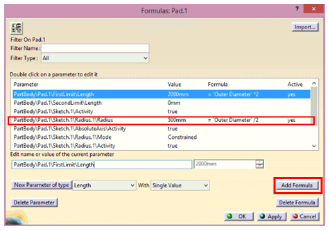
- Create Formulas:
- Outer Radius of tumbler is linked with the created parameter Outside Diameter as Outer Radius = Outer Diameter/2.
- Similarly, a formula is created to control Inner Diameter of tumbler as: Inner Radius = 0.45*Outer Diameter.
- Now, a formula is created to control the length of the tumbler by using Pad length as: Pad Length = 2* Outside Diameter.
- Finally, a formula is created to control the edge fillet of the Tumbler as: Edge Fillet Radius = 0.05*Outside Diameter.
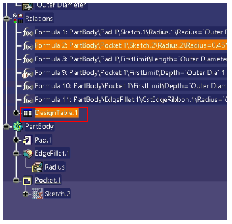
Now, Formulas need to be created to interlink various dimensions from the Driving Parameters. In this case, the inner diameter, length & edge fillet of tumbler must change as per the outer diameter of the tumbler. Hence, the following formulas are created:
![]()
![]()
![]()
- Create Design Table:
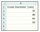
Now, it is decided that only four variants of tumblers will be produced of Outer Diameters 35mm, 40mm, 45mm & 50mm. Now, a design table is created that will have four configurations for making four variants of tumblers. In this case, a Design Table can have input values for a greater number of parameters with only one driving parameter.
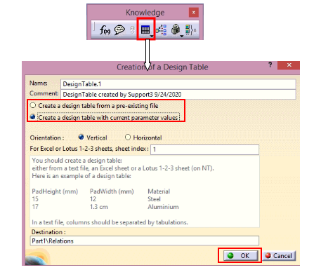
Design Table can be created either using any pre-existing design file or with current parameter values.
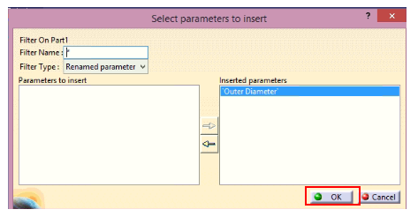
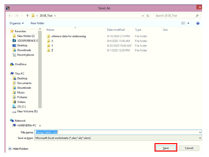
Design table is saved. Now, open the design table and add all the input values of parameters and save it.
Design Table is added under Relations node design in the specification tree. Double click on Design Table:
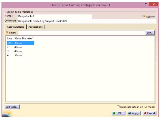
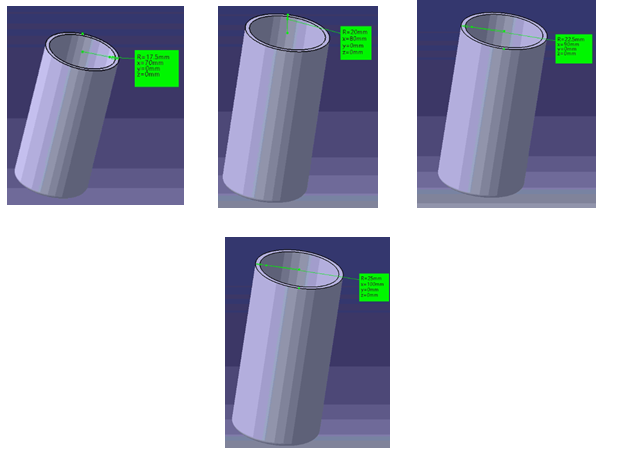
Now, any configuration can be selected and a new variant of tumbler can be obtained.
Mohit Aggarwal is an engineering professional with more than 4 years of experience. He is currently working as Application Engineer at EDS Technologies supporting multiple customers with CATIA V5, 3DEXPERIENCE application support. He also handles training sessions for multiple OEMs, suppliers, engineering service providers, and academia on various software tools and applications in CAD/CAM/CAE. He also creates content for EDST e-Learning platform. He has expertise in 3DEXPERIENCE with certification from Dassault Systèmes.