Composite Structure Investigation using ABAQUS Finite Element Solver
Introduction
Composite materials are less expensive and stronger in nature in comparison to conventional materials. They are formed from two or more constituent materials which are different in physical, mechanical and chemical properties. By nature, they are light in weight and extensively employed in spacecrafts, aircrafts, buildings, bridges, racing cars, bathtubs etc.
From a macroscopic point of view, composite materials are anisotropic in nature and require special tools such as numerical tool (FEM) and analytical method or mathematical tool to get insights when under failure, shock, impact or repeated cyclic stresses.
Keeping in mind the complexity and material orientation, this article captures the three-dimensional behavior of composite materials.
Geometry and Meshing
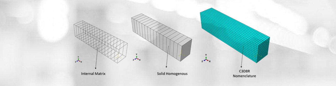
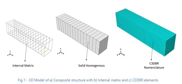
A solid homogenous part is created with internal partition and defined using offset options. Inside the solid homogenous part, a set of matrices are created.
For meshing, 8-node linear brick, reduced integration and hourglass control (C3D8R) were applied as shown in Fig 1.
Material
Elastic properties under engineering constant are defined during material assignment.
Material, name = “Composite Materials”
Elastic, type = ENGINEERING CONSTANTS
150000, 9000, 9000, 0.34, 0.34, 0.4, 5000, 5000, 5000
Loading and Boundary Conditions
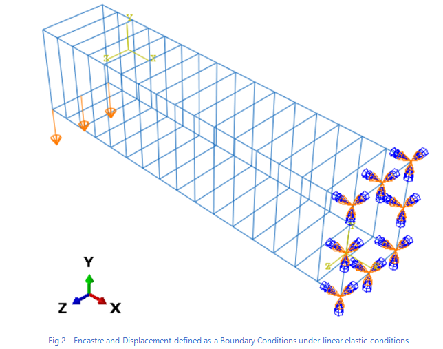
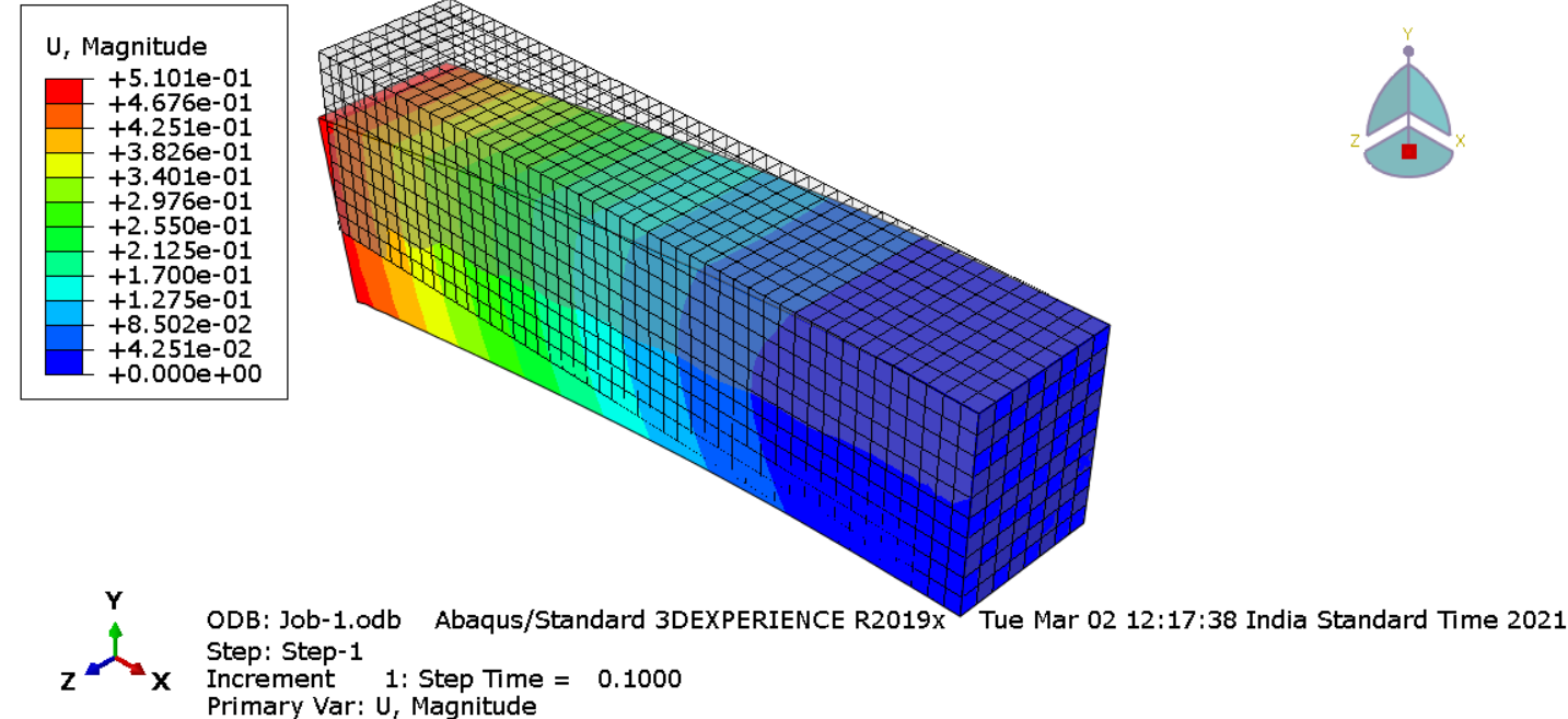
The simulation is performed under static conditions. During the first step, composite structure remains at static conditions. Both sections internally and externally are under static conditions. During the second step, one side of the structure remains under ENCASTRE conditions (U1-U2-U3-UR1-UR2-UR3 = 0). The second side is experiencing a displacement of -5 mm in Z – direction to generate the stress wave propagation as shown in Fig 2. The holistic idea is to see how internal stress is propagating within the structure.
The complete analysis (Pre + Post + Solver) is simulated in ABAQUS/ CAE code.
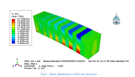
Results and Visualization
Stress distribution within the internal and external structure is calculated using path feature. Internal matrix experiences slightly lesser tensile stress when compared to external structure under Encastre conditions. Internal matrix which is close to Encastre conditions experiences higher compressive stress.
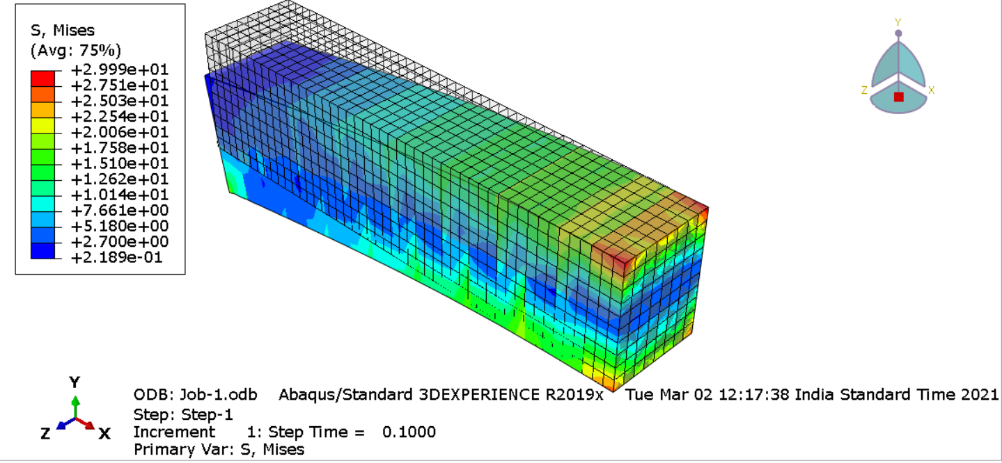
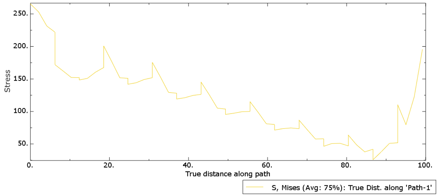
Mises stress components at integration points
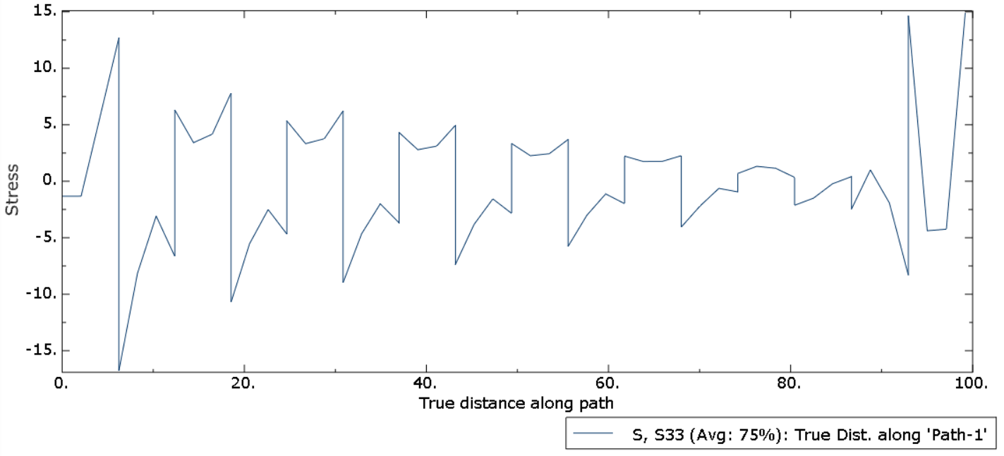
Mises stress components at integration points in S33 direction
Conclusion
The behavior of composite materials is studied using ABAQUS FEM Code. The main objective is to see how the stresses are distributed within the structure (Matrix). ABAQUS helps in predicting the behavior of composite materials subjected to displacement. The approach mentioned in this article can be used in a more complex way by varying the internal matrix dimensions. The matrix can be placed in dissimilar alignment also.
ABAQUS offers higher degree of autonomy in pre- and post-processing. It helps in gaining insights when composite materials are subjected to different conditions.
Varun is working with EDS Technologies as a SIMULIA Consultant. He has published more than 12 research papers in International Journals. He is the recipient of Marie Skłodowska – Curie Actions and OEAD International Mobility Fellowship. He has more than 6 years of R&D experience in the field of FEA. He has conducted R&D for Tata Steel, Ijmuiden, Netherlands in identifying the best refractory material for the blast furnace. He has carried out independent research of pore size distribution and void ratio (Geomechanics). He has performed experiments to check infiltration behavior and high-and-low temperature experiments in FH – Jena, Germany. He has done his Masters from University of Applied Sciences, Jena, Germany.