Measuring Inertia()

The Measure Inertia command lets you measure:

  • 3D inertia properties of surfaces and volumes

  • 2D inertia properties of plane surfaces. (explained below)

Measuring 2D Inertia

This task explains how to measure the inertia properties of plane 2D surfaces.

You can measure the area, center of gravity, principal moments, inertia matrix as well as the principal axes.

You can measure the inertia properties of plane surfaces including DMU sections. The area of the surface is also calculated.

  • Step-by-Step Scenario

  • Customizing Your Measure

Notes: You cannot measure inertia properties of either wireframe or infinite elements.

Step-by-Step Scenario

  1. Click Measure Inertia . In DMU, you can also select Analyze > Measure Inertia from the menu bar. The Measure Inertia dialog box appears.

  2. Click Measure 2D Inertia

    Dialog box options

    • A Keep Measure option in the dialog box lets you keep current and subsequent measures as features. Some measures kept as features are associative and can be used as parameters.

      Note: This option is not available in the Drafting workbench.

    • An Export option lets you write results to a text file.

    • A Customize... option lets you define what will be computed and displayed in the dialog box.

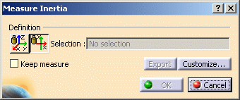
  3. Click to select a plane 2D surface in the geometry area or the specification tree. The Dialog Box expands to display the results for the selected item.

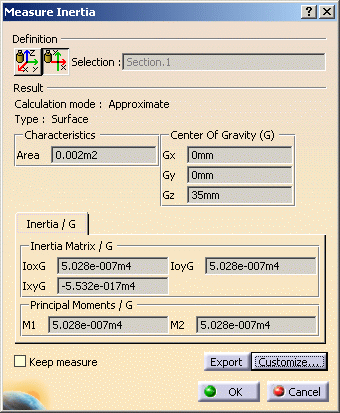
    The dialog box identifies the selected item, in our case a DMU section, and indicates whether the calculation is exact or approximate:

    • In Design mode, measures access exact data and wherever possible true values are given. Note that it is possible to obtain an exact measure for most items in design mode.

    • In Visualization mode, measures are made on tessellated items and approximate values are given.

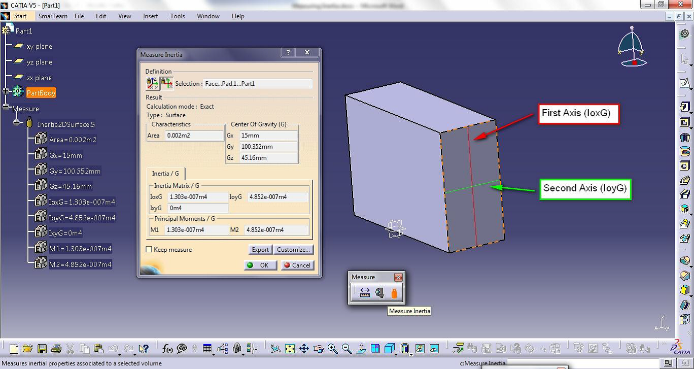
    In addition to the center of gravity G, the principal moments of inertia M and the matrix of inertia, the dialog box also gives the area of the selected item.

    The center of gravity G is computed with respect to the document axis system. The matrix of inertia is expressed in an axis system whose origin is the center of gravity and whose vectors are the axes of inertia.

    Notes:

    • The matrix of inertia and the principal moments do not take density into account.

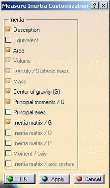
    • You can also compute and display the principal axes A. To do so, you must first activate the appropriate option in the Measure Inertia Customization dialog box.

    The number of decimal places, the display of trailing zeros and limits for exponential notation is controlled by the Units tab in the Options dialog box (Tools > Options, General > Parameters and Measure).

    To find out more about notations used

    In the Geometry Area

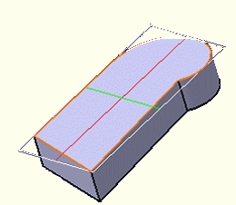
    The axes of inertia are highlighted and a bounding box parallel to the axes and bounding the selected item also appears.

    To obtain the same type of inertia matrix for similar shapes independent from the space orientation of the surface being measured (i.e. invariant); the x-axis is set along the Principal Moment axis with the smallest value (M1), i.e. along the longest side (red) and the y-axis is set along the second Principal Moment axis (M2) (green).

    Principal Axis matrix (A) expresses the axes orientations in the Global Axis System.

    Color coding of axes:

    • Red: axis corresponding to the first principal axis A1

    • Green: axis corresponding to the second principal axis A2

    The principal axes are invariant within the object i.e., they are independent from the object's space orientation.

    When you move the cursor over the geometry or specification tree, its appearance changes to reflect the measure command you are in.

  4. Click OK in the Measure Inertia dialog box. If you checked the Keep Measure option in the Measure Inertia dialog box, your measures are kept as features.

Customizing Your Measure

You can, at any time, define what will be computed and displayed in the tabs of the Measure Inertia dialog box.

When measuring 2D plane surfaces, in addition to the properties computed by default, you can compute and display the principal axes.

Click Customize... in the Measure Inertia dialog box. The Measure Inertia Customization dialog box opens.

Note: The inertia properties checked here are also the properties exported to a text file.

  1. Click the appropriate options:

    • Principal axes

  2. Click Apply or OK in the Measure Inertia Customization dialog box when done.