|
| What is DFM? |
|
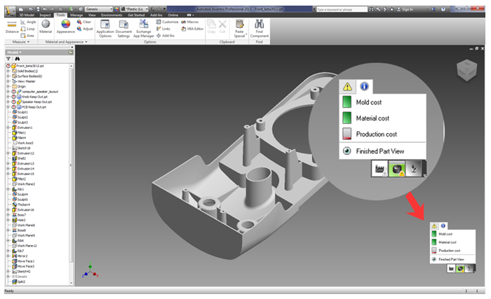
Design for Manufacturing(DFM) helps product designers create digital prototypes with manufacturability in mind. DFM Tool works within your existing 3D CAD system (Ie. Inventor/ Product Design Suite) to provide directional feedback on manufacturability, costs and sustainability as you design.
|
| |
| About Autodesk Simulation DFM |
Autodesk Simulation DFM software gives you manufacturability feedback at the early stage in the design process as one creates new CAD geometry. It also scans ones 3D CAD geometry providing feedback on nominal wall thickness, draft angles, material cost, recyclability, sink marks and more.
Autodesk Simulation DFM can also evaluate each design decision relating to ones injection moulded plastic part as you make it.
|
| |
 |
| |
| Who should use it? |
Decisions that product designers make influences and often determines downstream decisions relating to material choices, manufacturing process and through that nearly all aspects of product cost, form-fit and function sustainability.
It is estimated that early design decisions can contribute to as much as 70 to 80% of the manufacturing costs of a product! (*Ullman, D. G. (1992). The Mechanical Design Process, McGraw Hill, New York. )
|
| |
| When should I use it? |
Traditional simulation tools mean that first one must design and then one can simulate. Anything one finds in the results from the analysis is then interpreted and changes are made to the design to improve the part. Good workflow – defects can be found prior to starting the mold design much before going in for production thus saving significant time and cost that will be incurred in finding them at later stage in the design to manufacture process.
But there is still room to improvise upon; ideally one would want to know how each decision taken by a product designer in designing impacts manufacturability, costs and also environment. Design and simulation should be done concurrently so that one knows the impact of each design change undergone.
|
| |
| Why should an Analyst be keen for a Product Designer to use it? |
The cost of a design change increases significantly the closer one gets to manufacture. Identifying and eliminating potential molding problems at early stage is important for both product designers and analysts.
Potential design problems can be resolved allowing analysts more time and opportunity to perform detailed part and process optimization prior to manufacturing.
DFM provides a significant means of communication for both product designers and analyst to work with manufacturing groups and understand the impact of their design.
|
| |
| How are the indicators displayed? |
The easy to understand indicators give you valuable input upfront in the design process where it is most impactful and updates just as fast as one can create the 3D CAD geometry. A quick glance at the always on green/yellow/red indicator lets one know if the design change affects the overall manufacturability,cost and/or environmental footprint.

Yield symbols illustrate the potential for best practice violations of plastic part design (poor draft angles, thick parts, long cycle times etc…)

|
|
| What analysis results and advice are behind these indicators? |
Manufacturability
- Wall thickness : Ideally a plastic part should have an even wall thickness across the entire part otherwise quality problems may occur.
- Undercuts : An undercut is a design feature that interferes with the ejection of a molded part from the mold. An undercut can include features such as holes or boses that are not aligned with the direction of ejection, threaded sections and snap fingers.
- Draft angle : A draft angle is a slight taper added to assist in the ejection of the molded part from the mold. Surfaces parallel to the direction the part is ejected in; will cause difficulties in production.
- Weld Lines : A weld line on plastic parts can cause structural problems and/or be visually unacceptable.
- Sink marks : Sink marks result from localized shrinkage of the material at thick sections of the part.
- Filling : The Filling result can be used to show how molten plastic will fill a region within the mold cavity using the injection molding process.
Cost efficiency
- Mold cost : The size and complexity of a part along with the number and position of injection locations will determine the mold cost.
- Material cost : The size of the part and the relative cost of the selected material combine to determine the material cost.
- Production cost : The time it takes to manufacture a part and the associated costs are represented in the Production cost element.
Plastic material impact
- Carbon footprint : The carbon footprint is a measure of the amount of carbon dioxide gas produced by the production of the part.
- Embodied energy : The embodied energy is the total energy required in the making of a part. Typically 70-90% of this energy is associated with manufacturing the raw material.
- Recyclability : The recyclability of a material is a measure of the percentage of the material that is recovered as scrap and subsequently reprocessed into useful products.
- Embodied water : Embodied water is a measure of the amount of water required to produce the selected material.
|